Optical fiber cutting device

A cutting device and optical fiber technology, which is applied in the coupling of optical waveguides and other directions, can solve the problems of inability to cut large-diameter optical fibers, poor quality of the end face, and uneven end face, so as to improve the cutting efficiency of the optical fiber, avoid the limitation of the size of the optical fiber, and the operation simple effect

Pending Publication Date: 2020-09-22
蚌埠锐光仪器设备有限公司
View PDF7 Cites 2 Cited by
  • Summary
  • Abstract
  • Description
  • Claims
  • Application Information

AI Technical Summary

Problems solved by technology

[0003] However, the existing optical fiber cutting instruments mainly rely on manual operation of the cutter to cut the optical fiber, and can only cut the optical fiber with a small diameter, and cannot cut the optical fiber with a large diameter. poor disadvantage

Method used


Image

  • Optical fiber cutting device
  • Optical fiber cutting device
  • Optical fiber cutting device

Examples


Embodiment Construction

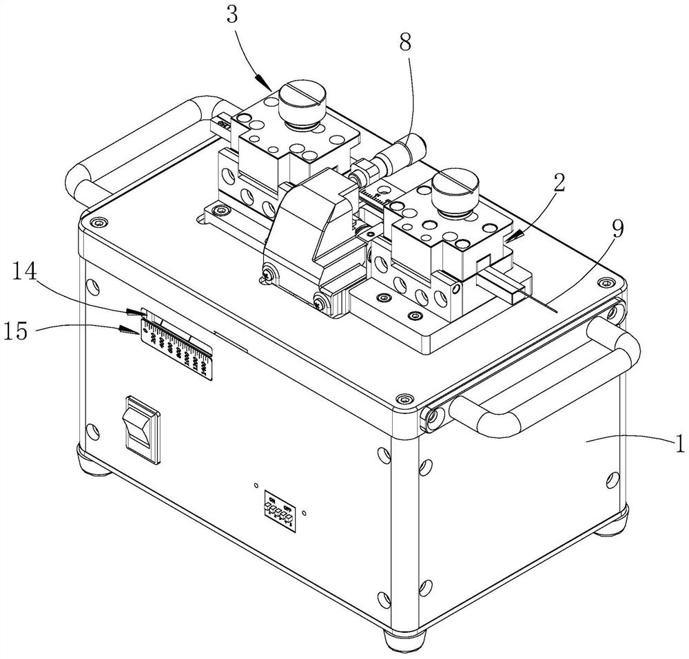
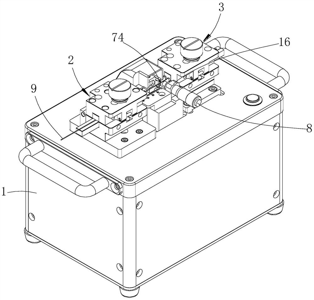
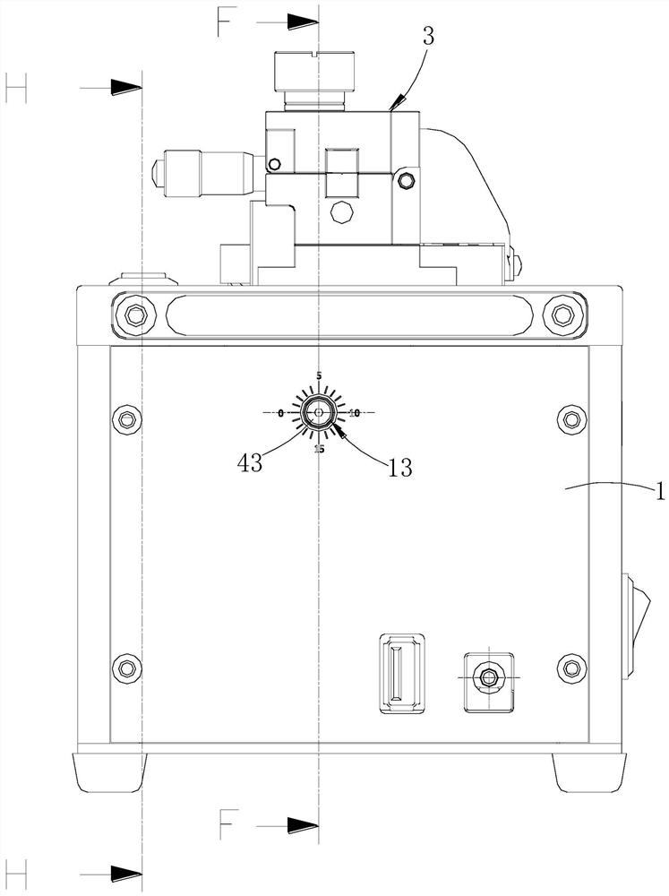
[0027] Such as Figures 1 to 8 shown

[0028] The optical fiber cutting device includes a box body 1, a pre-tensioning assembly, an ultrasonic cutting assembly, a cutting knife 74, a reset assembly, two sets of sliding assemblies and two sets of clamping mechanisms.

[0029] The box body 1 is generally in the shape of a cuboid, and the inside of the box body 1 is provided with a cavity 11. Two sets of clamping mechanisms are located on the upper side of the box body 1, and the two sets of clamping mechanisms are located on the left and right sides of the upper end surface of the box body 1. Tightening mechanism is the first clamping mechanism 2 and the second clamping mechanism 3, and the structure of the first clamping mechanism 2 and the second clamping mechanism 3 is identical;

[0030] Take the first clamping mechanism 2 as an example to introduce its structure in detail. The first clamping mechanism 2 is fixed on the right side of the upper end surface of the box body 1 ...


PUM


Abstract

The invention provides an optical fiber cutting device. The optical fiber cutting device comprises a cutter, a first clamping mechanism, a second clamping mechanism, a box body, a pre-pulling assemblyand an ultrasonic cutting assembly, the first clamping mechanism is fixedly connected to the upper end surface of the box body; the upper end of a connecting plate of the pre-pulling assembly is fixedly connected with the second clamping mechanism; a kidney-shaped hole allowing a connecting plate to move is formed in the upper end face of the box body, the connecting plate stretches into a cavityof the box body, a guide plate is fixed in the cavity of the box body, an adjusting bolt is matched with a threaded hole of the guide plate, one end of a pre-tensioning spring is fixed to the connecting plate, and the other end of the pre-tensioning spring is fixed to the end of the adjusting bolt. The two ends of a rotating shaft of an ultrasonic cutting assembly are supported on the box, the cutter is fixedly installed on the rotating shaft, and a servo motor rotates through a rotating shaft of a conveying belt. The optical fiber cutting device has the advantages that operation is simple, the optical fiber end surface quality and the optical fiber cutting efficiency are improved, the ultrasonic cutting assembly can be used to cut optical fibers with different sizes and diameters flexibly, and the limitation on the optical fiber size during manual cutting is avoided.

Description

technical field [0001] The invention relates to an optical fiber cutting device. Background technique [0002] Optical fiber cutters are mainly used for cutting optical fibers. The quality of fiber cutting mainly depends on whether the end face of the fiber is smooth, the angle of the end face, etc., and also directly determines whether the fiber splicing can meet the technical requirements of the project. At present, the main structure of optical fiber cutting equipment includes a base, a cutting knife and two sets of clamping mechanisms. The two sets of clamping mechanisms are distributed on both sides of the base. The two sets of clamping mechanisms can clamp the optical fiber. The cutting is between the two sets of clamping mechanisms. During the interval, the cutting knife can move along the gap between the clamping mechanisms, and the moving track of the cutting knife passes through the optical fibers clamped by the two sets of clamping mechanisms. [0003] However, ...

Claims


Application Information

Patent Timeline
Patent Type & Authority Applications(China)
IPC IPC(8): G02B6/25
CPCG02B6/25
Inventor 程飞刘顺贾翔宇
Owner 蚌埠锐光仪器设备有限公司
Why Eureka
Try Eureka