Optical imaging lens with high light flux and large image surface

An optical imaging lens, a large-pass light technology, applied in the field of lenses, can solve the problems of low pixels, unable to meet the intelligent transportation system, low resolution, etc., achieve high pixels, avoid edge darkening and color cast problems, and high resolution. Effect

Pending Publication Date: 2020-09-22
XIAMEN LEADING OPTICS
View PDF0 Cites 0 Cited by
  • Summary
  • Abstract
  • Description
  • Claims
  • Application Information

AI Technical Summary

Problems solved by technology

However, the optical imaging lenses currently used in intelligent transportation systems have low resolution and low pixels; when used in high and low temperature environments, the out-of-focus is serious; the image plane in the 16mm focal length segment is small, generally only reaching Φ16mm; Generally, it is relatively small. In low-light environment, the amount of incoming light is less, and the shooting image is darker; when the image surface is larger, the incident angle of the chief ray of CRA is larger, greater than 12°, and it is easy to match with the sensor of a smaller CRA. Causes the problem of dark edges and color cast, which can no longer meet the increasing requirements of intelligent transportation systems, and urgently needs to be improved

Method used


Image

  • Optical imaging lens with high light flux and large image surface
  • Optical imaging lens with high light flux and large image surface
  • Optical imaging lens with high light flux and large image surface

Examples


Embodiment 1

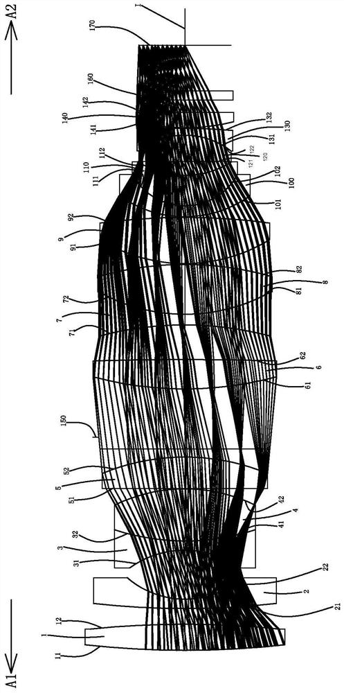
[0088] Such as figure 1 As shown, an optical imaging lens includes a first lens 1, a second lens 2, a third lens 3, a fourth lens 4, a fifth lens 5, a light Diaphragm 150, sixth lens 6, seventh lens 7, eighth lens 8, ninth lens 9, tenth lens 100, eleventh lens 110, twelfth lens 120, thirteenth lens 130, fourteenth lens 140, protective sheet 160 and imaging surface 170; the first lens 1 to the fourteenth lens 140 each include an object side facing the object side A1 and allowing the imaging light to pass through and an image side facing the image side A2 and allowing the imaging light to pass through .

[0089] The first lens 1 has a positive refractive power, the object side 11 of the first lens 1 is convex, and the image side 12 of the first lens 1 is convex.

[0090] The second lens 2 has a negative refractive power, the object side 21 of the second lens 2 is convex, and the image side 22 of the second lens 2 is concave.

[0091] The third lens 3 has a negative refractive...

Embodiment 2

[0115] The concave-convex surface shape and refractive index of each lens in this embodiment are the same as those in the first embodiment, and only the optical parameters such as the radius of curvature of the lens surface and the thickness of the lens are different.

[0116] The detailed optical data of this specific embodiment are shown in Table 2-1.

[0117] Detailed optical data of Table 2-1 Example 2

[0118]

[0119]

[0120] Please refer to Table 5 for the values ​​of the relevant conditional expressions in this specific embodiment.

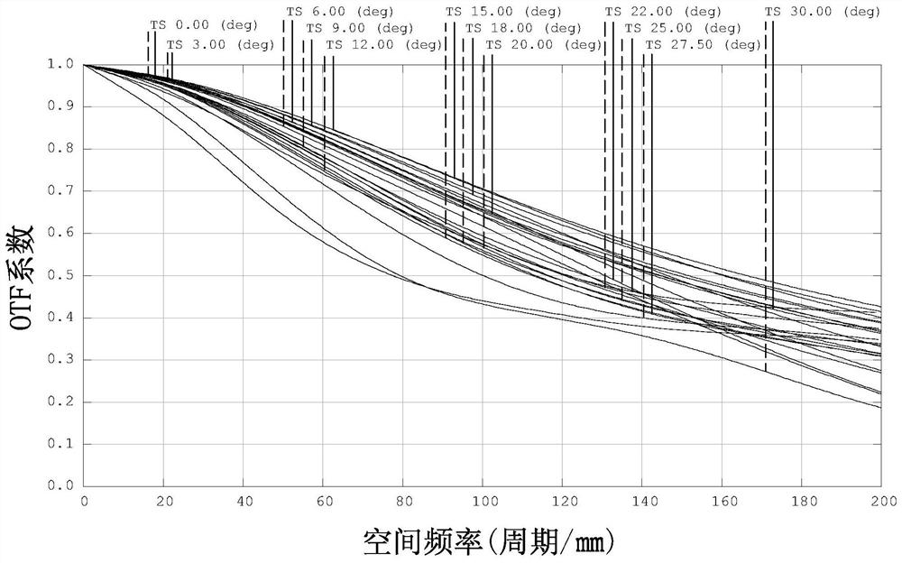
[0121] For the resolution of this specific embodiment, please refer to Figure 7-9 , it can be seen from the figure that the transmission is well controlled, the resolution is high, the resolution of the full field of view can reach 200lp / mm, and it can support 20 million pixels, and it is almost not out of focus at high and low temperatures; please refer to the sector diagram Figure 10 , see the lateral color difference diagram ...

Embodiment 3

[0124] The concave-convex surface shape and refractive index of each lens in this embodiment are the same as those in the first embodiment, and only the optical parameters such as the radius of curvature of the lens surface and the thickness of the lens are different.

[0125] The detailed optical data of this specific embodiment are shown in Table 3-1.

[0126] Detailed optical data of the third embodiment of table 3-1

[0127]

[0128]

[0129] Please refer to Table 5 for the values ​​of the relevant conditional expressions in this specific embodiment.

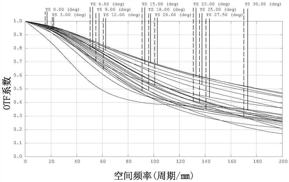
[0130] For the resolution of this specific embodiment, please refer to Figure 12-14 , it can be seen from the figure that the transmission is well controlled, the resolution is high, the resolution of the full field of view can reach 200lp / mm, and it can support 20 million pixels, and it is almost not out of focus at high and low temperatures; please refer to the sector diagram Figure 15 , see the lateral color dif...


PUM


Abstract

The invention relates to the technical field of lenses. The invention discloses an optical imaging lens with high light flux and a large image surface. The optical imaging lens comprises fourteen lenses, the first lens, the fourth lens, the sixth lens, the eighth lens and the ninth lens are convex-convex lenses with positive refractive indexes; the second lens and the tenth lens are convex-concavelenses with negative refractive indexes; the third lens and the seventh lens are concave-concave lenses with negative refractive indexes; the fifth lens and the twelfth lens are plano-convex lenses with positive refractive indexes; the eleventh lens is a convex-concave lens with a positive refractive index; the thirteenth lens is a concave-convex lens with negative refractive index; the fourteenth lens is a convex-plane lens with a positive refractive index; the third lens and the fourth lens are glued with each other; the tenth lens and the eleventh lens are glued with each other; and the twelfth lens and the thirteenth lens are glued with each other. The optical imaging lens has the advantages of high resolution and high imaging quality; the image surface is large; light transmission ishigh; high and low temperature defocusing is low or no defocusing is caused; and a CRA main light incident angle is realized.

Description

technical field [0001] The invention belongs to the field of lens technology, and in particular relates to an optical imaging lens with a large image surface. Background technique [0002] With the continuous advancement of science and technology and the continuous development of society, optical imaging lenses have also developed rapidly in recent years, and are widely used in smart phones, tablet computers, video conferencing, vehicle monitoring, security monitoring, machine vision, intelligent transportation Systems and other fields, therefore, the requirements for optical imaging lenses are getting higher and higher. [0003] In intelligent transportation systems, the performance of optical imaging lenses is critical and will affect the reliability of the entire system. However, the optical imaging lenses currently used in intelligent transportation systems have low resolution and low pixels; when used in high and low temperature environments, the out-of-focus is seriou...

Claims


Application Information

Patent Timeline
Patent Type & Authority Applications(China)
IPC IPC(8): G02B13/00
CPCG02B13/00
Inventor 曹来书苏炳坤李雪慧
Owner XIAMEN LEADING OPTICS
Why Eureka
Try Eureka