Push rod device with force control

A pusher, pressure sensor technology, applied in the direction of controlling mechanical energy, belt/chain/gear, connecting with control/drive circuit, etc. Reliability, improve anti-interference ability, good-looking effect

Inactive Publication Date: 2020-09-22
NANJING UNIV OF AERONAUTICS & ASTRONAUTICS
View PDF0 Cites 1 Cited by
  • Summary
  • Abstract
  • Description
  • Claims
  • Application Information

AI Technical Summary

Problems solved by technology

There are many transmission mechanisms in the prior art, and the transmission mechanisms used on large equipment are more precise, the assembly steps are complicated, and the cost is relatively high
If this kind of transmission mechanism is used in some common equipment and furniture in daily life, the cost will increase and it is not applicable

Method used


Image

  • Push rod device with force control
  • Push rod device with force control

Examples


Embodiment Construction

[0021] The embodiments of the present invention are described in detail below. Examples of the embodiments are shown in the accompanying drawings, wherein the same or similar reference numerals indicate the same or similar elements or elements with the same or similar functions. The following embodiments described with reference to the accompanying drawings are exemplary, and are only used to explain the present invention, and cannot be construed as limiting the present invention.

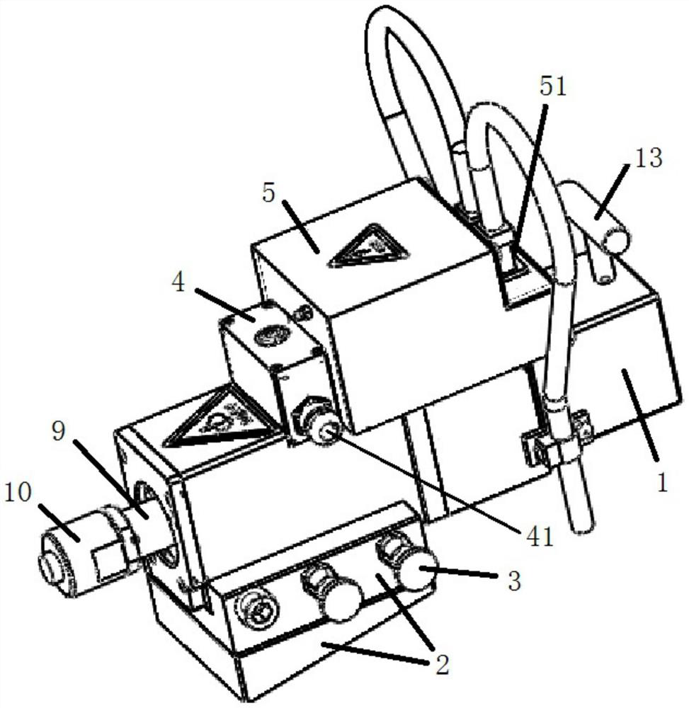
[0022] A push rod with force control, such as figure 1 As shown, the push rod body 1 and the independent base 2 are included, and the push rod body 1 is fixed on the independent base 2 through the plunger knob 3. The upper surface of the rear end of the push rod body 1 is provided with a handle 13 for convenient installation and operation.

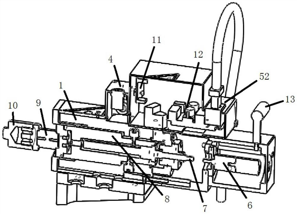
[0023] The internal cavity of the push rod body 1 is provided with a DC brushless servo motor 6, a ball screw 7 and a nut sleeve 8. The nut sleeve 8 is arranged in...


PUM


Abstract

The invention provides a push rod device with a force control function. The push rod device comprises a push rod device body and an independent base, wherein the push rod device body is fixed on the independent base through a plunger knob, a power supply access box and a control box are both installed on the push rod device body, a direct-current brushless servo motor, a ball screw and a nut sleeve are arranged in an inner cavity of the push rod device body, a nut sleeve is arranged on the front portion in the cavity, a ball screw is arranged in the nut sleeve in a penetrating mode, a linear push rod extending out of the cavity is fixed to a front end of the ball screw, a pressure sensor is installed at a front end of the linear push rod, the pressure sensor is sleeved with a pressure head, and a rear end of the ball screw is connected with a direct-current brushless servo motor, and a pressure sensor transmitting module and a motor driving controller are arranged in the control box. The push rod device is advantaged in that the force control function is achieved through linear extension and contraction, the force control function and the stress state maintaining function are achieved, a high-speed real-time bus communication interface is achieved, the structure is light, and installation is convenient.

Description

Technical field [0001] The invention relates to the technical field of transmission mechanisms, in particular to a push rod with force control. Background technique [0002] The mechanical transmission mechanism can change the mode, direction or speed of the movement provided by the power, and it can be used purposefully by people. There are many transmission mechanisms in the prior art, and the transmission mechanism used in large-scale equipment is relatively precise, has complicated assembly steps, and has a relatively high cost. If this kind of transmission mechanism is used in some common equipment and furniture in life, its cost will increase and it is not applicable. Summary of the invention [0003] The technical problem solved by the present invention is to provide a push rod with force control, which realizes the force control function by linear extension and contraction, and has the function of force control and force state maintenance, has a high-speed real-time bus c...

Claims


Application Information

Patent Timeline
IPC IPC(8): H02K7/06H02K11/20H02K11/22H02K11/33F16H25/20
CPCF16H25/20F16H2025/2075H02K7/06H02K11/20H02K11/22H02K11/33
Inventor 张得礼逯轩王珉鲍益东金霞陈文亮
Owner NANJING UNIV OF AERONAUTICS & ASTRONAUTICS
Why Eureka
Try Eureka