Atomization device capable of improving atomization effect and preventing liquid leakage

An atomization device and anti-leakage technology, which is applied in the treatment of atomizers, tobacco, etc., can solve the problems of affecting the experience, affecting the perception, and prone to spillage, so as to solve the problem of liquid leakage, uniform atomization and more Fully and enhance the effect of atomization effect

Pending Publication Date: 2020-09-25
DONGGUAN TELAKANG TECH CO LTD
View PDF0 Cites 3 Cited by
  • Summary
  • Abstract
  • Description
  • Claims
  • Application Information

AI Technical Summary

Problems solved by technology

like Figure 13a As shown, in the traditional technology, the heating wire is generally wound on the oil-conducting material to form an atomizing core, and the gas passes through the upper and lower sides of the atomizing core. Such a structure, in actual use, when excess liquid seeps out, it is very easy to overflow. If the overflow is sucked into the user's mouth, it will affect the experience. If the overflow overflows the outside of the electronic cigarette, it will affect the perception; Figure 13b As shown, there are also some ring-shaped oil-conducting materials, and the heat-generating element is placed inside the oil-conducting material. The oil-conducting material absorbs oil from the outside and is heated and atomized by the internal heating element. The gas also enters from the bottom and passes through the heat The internal channel of the component is then vented from above. This structure has the same problems as above.

Method used


Image

  • Atomization device capable of improving atomization effect and preventing liquid leakage
  • Atomization device capable of improving atomization effect and preventing liquid leakage
  • Atomization device capable of improving atomization effect and preventing liquid leakage

Examples


Embodiment Construction

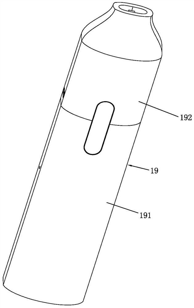
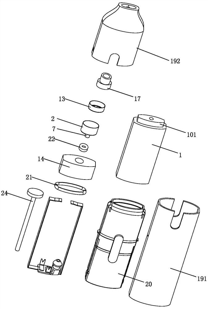
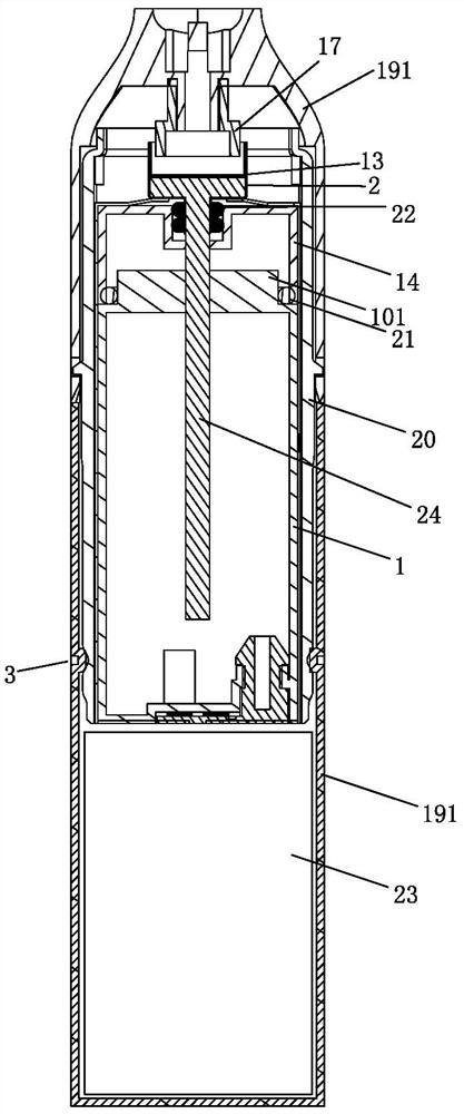
[0059] Please refer to Figure 1 to Figure 12 As shown, it shows the specific structure of various embodiments of the present invention. The atomizing device described in the present invention can be applied to products such as electronic cigarettes and medical atomizing devices; in this article, electronic cigarettes are taken as an example to describe in detail.

[0060] An atomization device that improves the atomization effect and prevents liquid leakage, comprising a liquid storage chamber 1, an atomization cup 2, an air inlet 3 and an air outlet pipe 4, wherein: the atomization cup 2 has an upper end opening, and the outlet The air pipe 4 extends into the atomizing cup 2 from the upper opening and maintains a gap with the inner bottom surface of the atomizing cup 2, and an air inlet channel 5 is formed between the outer circumference of the air outlet pipe 4 and the inner wall of the atomizing cup 2; The liquid in the chamber 1 enters the atomizing cup 2 and is heated a...


PUM


Abstract

The invention discloses an atomization device capable of improving atomization effect and preventing liquid leakage. The atomization device comprises a liquid storage cavity, an atomizing cup, an airinlet and an air outlet pipe, the atomizing cup is provided with an opening in the upper end, the air outlet pipe extends into the atomizing cup from the opening in the upper end and keeps a gap withthe inner bottom face of the atomizing cup, and an air inlet channel is formed between the periphery of the air outlet pipe and the inner wall face of the atomizing cup; liquid in the liquid storage cavity enters the atomizing cup to be heated and atomized into atomized matter, and external gas enters the atomizing cup through the gas inlet, the opening in the upper end of the atomizing cup and the gas inlet channel in sequence, is mixed with an atomized matter and then is exhausted from the gas outlet pipe. Thus, the atomizing cup can contain and adsorb redundant seeping liquid, and due to the fact that airflow does not form vertical through convection, the phenomenon that the liquid is sucked into the oral cavity of a user or overflows out of the electronic cigarette is avoided; meanwhile, due to the gas inlet mode and the gas flow direction, the gas and the atomized matter are contacted and mixed more fully, the atomized matter is taken away more timely, and the atomization efficiency and the atomization effect are effectively improved.

Description

technical field [0001] The present invention relates to the field of atomization devices, in particular to an atomization device that improves the atomization effect and prevents liquid leakage, which is mainly but not limited to be used in electronic cigarettes, medical atomization devices, and the like. Background technique [0002] There is an atomization device, which heats and atomizes a liquid through a heating device to form a mist or mist for human inhalation. It is usually widely used in electronic cigarettes, medical atomization devices and other products. [0003] Taking e-cigarettes as an example, as a substitute for cigarettes, e-cigarettes are mainly used to quit smoking and replace cigarettes. Because of their advantages of safety, convenience, health, and environmental protection, e-cigarettes have attracted more and more attention and favor from people. The electronic cigarettes in the prior art all include an atomizer. The atomizer usually has an oil storag...

Claims


Application Information

Patent Timeline
Patent Type & Authority Applications(China)
IPC IPC(8): A24F40/10A24F40/42A24F40/40A24F40/46A61M11/00
CPCA61M11/00A24F40/10A24F40/40A24F40/42A24F40/46
Inventor 肖鑫
Owner DONGGUAN TELAKANG TECH CO LTD
Why Eureka
Try Eureka