Pyrotechnic composition drying system

A drying system and pyrotechnic powder technology, which is applied in the field of fireworks pyrotechnic powder drying system, can solve the problems of insufficient power, too much energy consumption, disappearance, etc., to reduce the use of electric auxiliary heating, increase the temperature of the working environment, and reduce the load on the compressor Effect

Inactive Publication Date: 2015-07-29
CHANGSHA YUEQI ENERGY SAVING ELECTRICAL EQUIP CO LTD
View PDF15 Cites 7 Cited by
  • Summary
  • Abstract
  • Description
  • Claims
  • Application Information

AI Technical Summary

Problems solved by technology

[0003] 1. The thermal energy utilization rate is not high, and the energy consumption is still too large
Especially in winter when the temperature is low, the dependence on electric auxiliary heating is high, which has caused a great impact on the power grid. In particular, most of the fireworks and firecrackers production enterprises are located in rural areas, and rural electricity is generally insufficient, which affects normal production.
On the other hand, the direct dehumidification method adopted by the existing drying room, while discharging moisture, it also takes away part of the heat energy; at the same time, under high temperature conditions (such as 60°C or above), the ability of the moisture in the air to condense into liquid water decrease or even disappear
[0004] 2. There are potential safety hazards
In winter, the drying temperature is low, and resistance auxiliary heating is required. At the same time, there is a lack of dust suppression measures in the drying room. The resistance auxiliary device is installed in the drying room, which brings greater danger to the drying of pyrotechnic powder; in addition, the direct moisture discharge system The air in the air has not been dedusted, and some gunpowder dust is carried into the external environment, which is not only not conducive to environmental protection, but also leaves a safety hazard

Method used


Image

  • Pyrotechnic composition drying system
  • Pyrotechnic composition drying system
  • Pyrotechnic composition drying system

Examples


Embodiment Construction

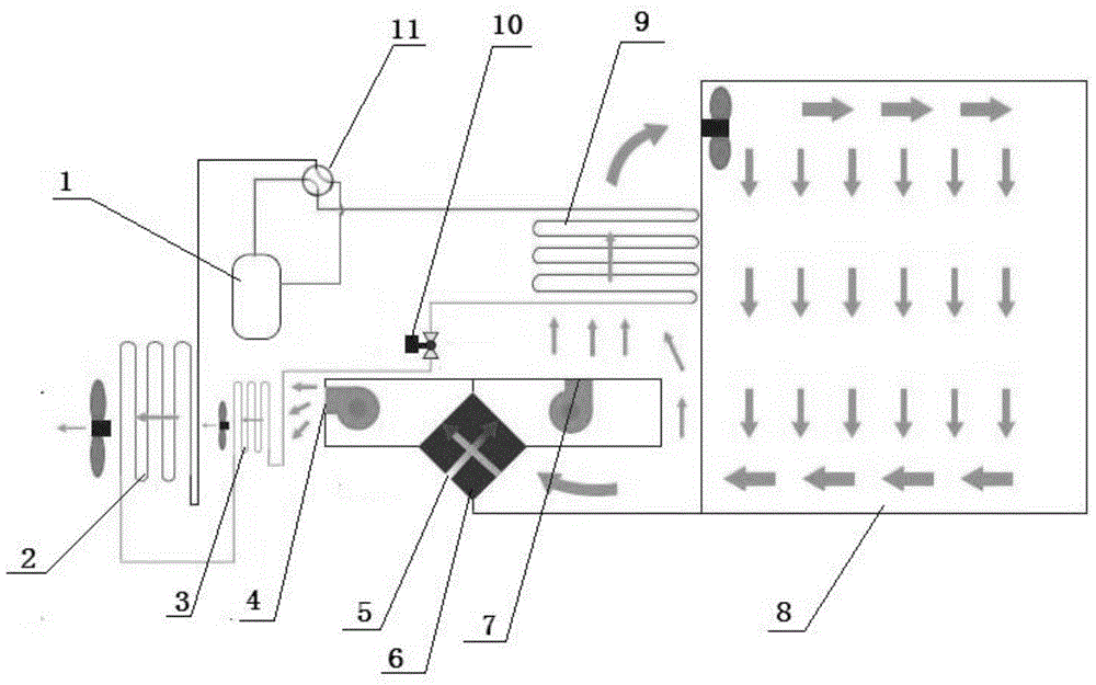
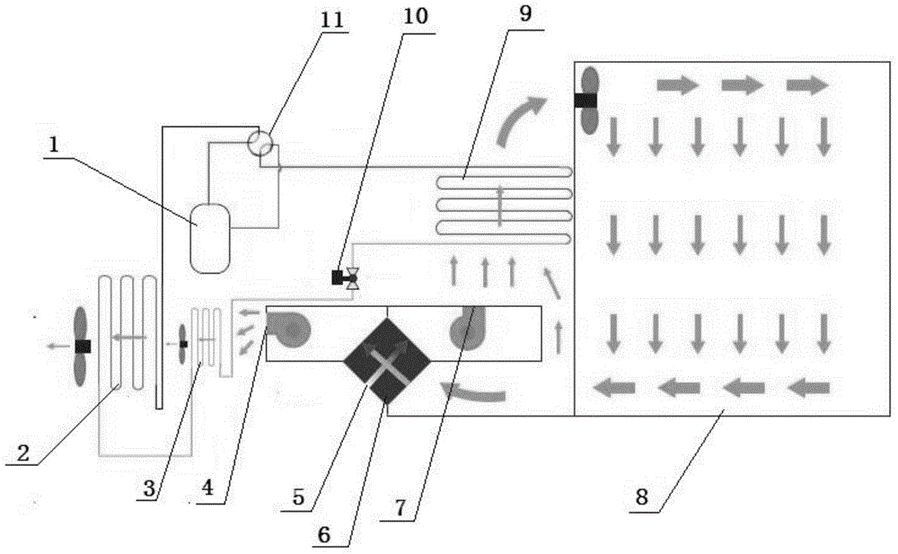
[0022] Referring to the accompanying drawings, reflecting a specific structure of the present invention, the pyrotechnic powder drying system includes an air source heat pump and a drying room 8, and the air source heat pump includes a working fluid pipeline connected to a compressor 1, a condenser / evaporator 9, a section The working medium circulation circuit composed of the expansion valve 10 of the flow device and the main evaporator / main condenser 2; the four-way valve 11 of the air source heat pump device is used to realize the conversion between the cooling mode and the heating mode.

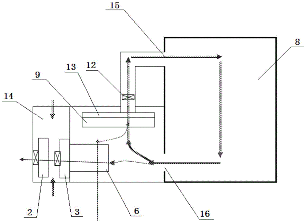
[0023] The air inlet and outlet of the drying room 8 are respectively connected to the air outlet and the air inlet of the condenser 9 to form a main air duct for circulating heating; the flow rate of the fan 12 of the main air duct is 2000-3500m 3 / h, the total pressure of the fan is 800-715Pa.

[0024] The main air duct is equipped with a fresh air replenishment channel and a dehumidific...


PUM


Abstract

The invention discloses a pyrotechnic composition drying system. The pyrotechnic composition drying system comprises an air source heat pump and a drying room, wherein an auxiliary evaporator is further arranged between a throttling device of the air source heat pump and a main evaporator; a heat exchanger is arranged between a fresh air supplementing channel and a dehumidification channel; humid and hot air in the dehumidification channel sequentially passes through the heat exchanger and the auxiliary evaporator and then enters a main evaporator chamber; an air inlet of the drying room is formed in the upper part of the drying room, and an air outlet of the drying room is formed in the lower part of the drying room; a top-to-bottom circulation mode of the hot air is formed in the drying room. The pyrotechnic composition drying system serves as a special drying system applicable to firework pyrotechnic compositions and has the advantages of better safety, energy conservation and environmental friendliness.

Description

technical field [0001] The invention relates to a drying system for fireworks and pyrotechnic powder. Background technique [0002] In recent years, in the fireworks and firecrackers industry, heat pump drying technology has been gradually promoted to the whole industry, which has improved production efficiency and reduced losses caused by weather changes. However, the existing heat pump drying technology generally has the following two problems: [0003] 1. The utilization rate of heat energy is not high, and the energy consumption is still too large. Especially in winter when the temperature is low, the dependence on electric auxiliary heating is high, which has caused a great impact on the power grid. In particular, most of the fireworks and firecrackers production enterprises are located in rural areas, and rural electricity is generally insufficient, which affects normal production. . On the other hand, the direct dehumidification method adopted by the existing drying...

Claims


Application Information

Patent Timeline
Patent Type & Authority Applications(China)
IPC IPC(8): F26B9/02F26B21/00F26B21/04
Inventor 刘若平
Owner CHANGSHA YUEQI ENERGY SAVING ELECTRICAL EQUIP CO LTD
Why Eureka
Try Eureka