A pipeline connection device for water conservancy engineering and its use method

A connection device and water conservancy engineering technology, applied in cleaning methods and appliances, chemical instruments and methods, cleaning hollow objects, etc., can solve the problems of not being able to ensure the safety of installation workers and convenient installation, wiping and cleaning, and the inability to scrape and adsorb the outer wall of the pipe.

Active Publication Date: 2021-10-26
宁夏丰泰建信实业发展有限公司
View PDF6 Cites 0 Cited by
  • Summary
  • Abstract
  • Description
  • Claims
  • Application Information

AI Technical Summary

Problems solved by technology

Although this patent can solve the problem of reducing the labor intensity of the staff and shortening the connection or disassembly process of the staff to the pipeline, it cannot solve the existence of scale, impurities and welding rust on the outer wall of the pipeline, and cannot scrape, absorb and wipe the outer wall of the pipeline. The safety of the installation workers cannot be guaranteed when installing the pipeline and the characteristics of convenient installation

Method used


Image

  • A pipeline connection device for water conservancy engineering and its use method
  • A pipeline connection device for water conservancy engineering and its use method
  • A pipeline connection device for water conservancy engineering and its use method

Examples


Embodiment 1

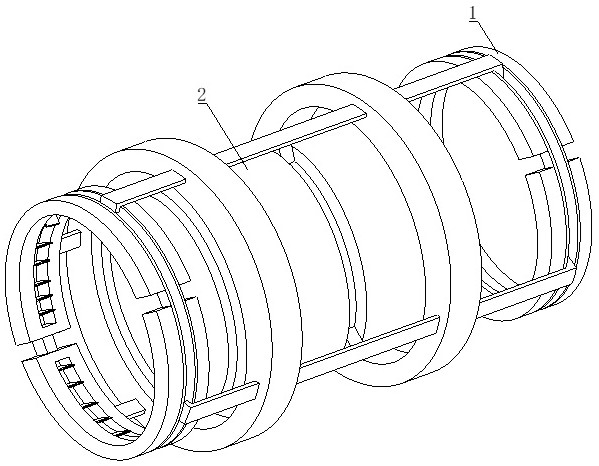
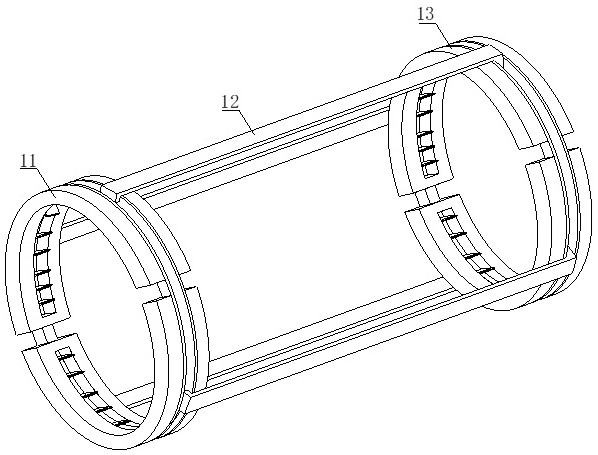
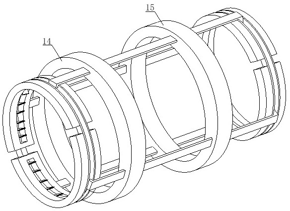
[0039] see figure 1 , figure 2 , image 3 , Figure 5 , Figure 8 and Figure 9 , a pipeline connection device for water conservancy projects, including a connection mechanism 1 and a drive mechanism 2, the connection mechanism 1 includes a first installation collar 11, a drive rod 12, a second installation collar 13, a first installation sleeve 14 and a second Mounting sleeve 15, the outer end of the first mounting ring 11 is equipped with a driving rod 12, the other end of the driving rod 12 is flexibly connected with the second mounting ring 13, and the outer ring of the driving rod 12 is equipped with a first mounting sleeve 14 , the right side of the first installation sleeve 14 is installed with the second installation sleeve 15, the driving mechanism 2 is installed in the inner cavity of the first installation sleeve 14 and the second installation sleeve 15, the driving mechanism 2 includes the assembly casing 21, Inner sliding mechanism 22, installation casing 23...

Embodiment 2

[0041] see Figure 4 , Figure 6 and Figure 7 , the first installation collar 11 includes a first assembly ring 111, a second assembly ring 112, an auxiliary outer ring groove 113, an inner cavity groove 114, a cleaning mechanism 115 and a movable telescopic rod 116, the side of the first assembly ring 111 An auxiliary outer ring groove 113 is installed at the end, and an auxiliary outer ring groove 113 is installed between the first assembly ring 111 and the second assembly ring 112, and the inner cavity walls of the first assembly ring 111 and the second assembly ring 112 are opened. There are inner cavity grooves 114, and the inner cavity wall annular array of the inner cavity grooves 114 is equipped with a cleaning mechanism 115, and the auxiliary outer ring grooves 113 are movably connected by a movable telescopic rod 116, and the driving rod 12 includes a driving carrier bar 121, a through hole 122 and Sliding meshing mechanism 123, the middle of the upper end of driv...


PUM


Abstract

The invention discloses a pipeline connection device for water conservancy projects and its use method. Although the existing technology can reduce the labor intensity of the staff and shorten the connection or disassembly process of the pipeline by the staff, it cannot solve the problem of scale spreading on the outer wall of the pipeline. , Impurities and welding rust, the outer wall of the pipeline cannot be scraped, adsorbed and wiped clean, and the safety of the installation workers and the characteristics of convenient installation cannot be guaranteed when installing the pipeline. Through the mechanical cooperation between the connecting mechanism and the driving mechanism, the present invention absorbs and cleans the scale, impurities and welding rust all over the outer wall of the pipeline, so as to ensure the safety of workers when installing the pipeline and to facilitate installation.

Description

technical field [0001] The invention relates to the technical field of water conservancy engineering, in particular to a pipe connection device for water conservancy engineering and a use method thereof. Background technique [0002] Water conservancy projects are projects built to control and allocate natural surface water and groundwater to achieve the purpose of eliminating harm and rejuvenating profits. Also known as water engineering. Water is an indispensable precious resource for human production and life, but its natural state does not fully meet human needs. Only by building water conservancy projects can we control water flow, prevent floods, and regulate and distribute water to meet the needs of people's life and production for water resources. Water conservancy projects need to build different types of hydraulic structures such as dams, dikes, spillways, sluices, water inlets, channels, canals, rafts, and fishways to achieve their goals. [0003] Patent No. CN...

Claims


Application Information

Patent Timeline
Patent Type & Authority Patents(China)
IPC IPC(8): B08B9/023
CPCB08B9/023
Inventor 郭云美
Owner 宁夏丰泰建信实业发展有限公司
Why Eureka
Try Eureka