
Vertical numerically-controlled lathe

A technology for CNC lathes and lathes, which is applied in the field of CNC lathes and can solve problems such as affecting the workpiece process.

Inactive Publication Date: 2020-09-25
广州佳优华信息科技有限公司
View PDF9 Cites 0 Cited by
  • Summary
  • Abstract
  • Description
  • Claims
  • Application Information

AI Technical Summary

Problems solved by technology

[0004] Aiming at an existing vertical numerical control lathe, when the workpiece is processed, a large amount of waste chips will be generated due to the cutting of the workpiece by the tool, and these waste chips are partially accumulated near the workpiece, so that the workpiece will be separated from the accumulated waste chips under high-speed rotation. Chips are rubbed against, causing dents on the surface of the workpiece to affect the technology of the workpiece. The present invention provides a vertical numerical control lathe to solve the above technical problems

Method used


Image

  • Vertical numerically-controlled lathe
  • Vertical numerically-controlled lathe
  • Vertical numerically-controlled lathe

Examples


Embodiment 1

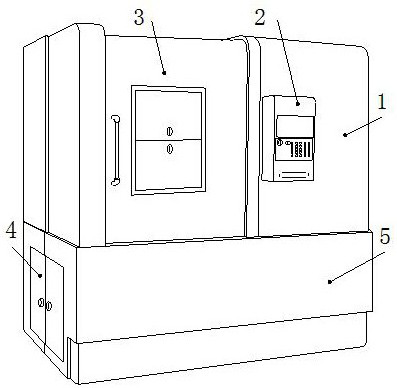
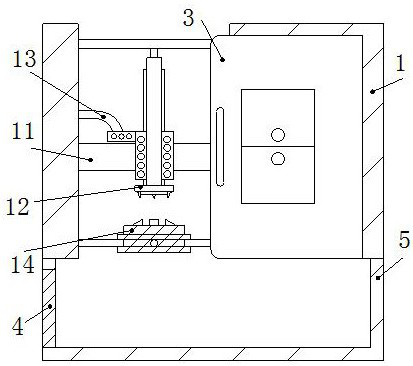
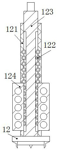
[0031] The present invention provides a vertical numerically controlled lathe, the structure of which comprises a lathe body 1, a control panel 2, a lathe door 3, an impurity removal cabinet 4, and a base 5, the bottom of the lathe body 1 is embedded and fixed on the upper surface of the base 5, and the control The plate 2 is installed on the front side of the lathe body 1, the lathe door 3 is connected to the front wall of the lathe body 1 through a gap, the impurity removal cabinet 4 is installed on the left side of the base 5, and the lathe body 1 includes a fixed frame 11, a tool 12. Control pipe 13, fixture 14, the left and right ends of the fixed frame 11 are respectively connected to the left and right inner walls of the lathe body 1 by welding, the tool 12 is connected to the front wall of the fixed frame 11 through a gap, and the end of the control pipe 13 is connected by bolts Connected to the left side of the tool 12, the outside of the bottom of the clamp 14 is conn...

Embodiment 2

[0037]The present invention provides a vertical numerically controlled lathe, the structure of which comprises a lathe body 1, a control panel 2, a lathe door 3, an impurity removal cabinet 4, and a base 5, the bottom of the lathe body 1 is embedded and fixed on the upper surface of the base 5, and the control The plate 2 is installed on the front side of the lathe body 1, the lathe door 3 is connected to the front wall of the lathe body 1 through a gap, the impurity removal cabinet 4 is installed on the left side of the base 5, and the lathe body 1 includes a fixed frame 11, a tool 12. Control pipe 13, fixture 14, the left and right ends of the fixed frame 11 are respectively connected to the left and right inner walls of the lathe body 1 by welding, the tool 12 is connected to the front wall of the fixed frame 11 through a gap, and the end of the control pipe 13 is connected by bolts Connected to the left side of the tool 12, the outside of the bottom of the clamp 14 is conne...


PUM


Abstract

The invention discloses a vertical numerically-controlled lathe. The vertical numerically-controlled lathe structurally comprises a lathe body, a control panel, a lathe door, a sweeps removal cabinetand a base; the bottom of the lathe body is embedded and fixed to the upper surface of the base; the control panel is installed on the front side of the lathe body; the lathe door is connected to thefront wall of the lathe body through a gap; and the sweeps removal cabinet is installed on the left side of the base in a matched mode. The vertical numerically-controlled lathe has the beneficial effects that a lifting rod is driven to move up and down through rotation of a rotary rod, thus, a tool moves up and down to machine a workpiece, meanwhile, the tool is horizontally fixed to a fixing frame through a fixing plate, the bottom of the tool is provided with four blades, and the used blades can be changed according to requirements in the workpiece machining process to machine the workpiece; the lathe door is opened so that the workpiece can be put into a storage cavity; clamping plates are driven to stretch out to clamp the workpiece tightly through a telescopic barrel, a guide rollerrotating anticlockwise drives a push plate to push sweeps onto a conveying belt, then, the sweeps are discharged into the base, and accordingly, the situation that the sweeps are stacked nearby the workpiece, thus, the surface of the workpiece is rubbed and dented, and the workpiece technology is influenced is avoided.

Description

technical field [0001] The invention relates to the field of numerically controlled lathes, in particular to a vertical numerically controlled lathe. Background technique [0002] Vertical CNC lathe is a kind of equipment that controls the tool according to the program written in the computer, and the through-pipe tool automatically cycles the workpiece to make the processed workpiece meet the required requirements. When processing the workpiece, close the lathe door to prevent machining. The waste debris generated in the process is splashed, which is convenient for cleaning and cleaning the waste debris. [0003] At present, there is an existing vertical numerical control lathe. When the workpiece is processed, a large amount of waste chips will be generated due to the cutting of the workpiece by the tool. Chips will be rubbed, causing dents on the surface of the workpiece to affect the process of the workpiece. Contents of the invention [0004] Aiming at an existing v...

Claims


Application Information

Patent Timeline
IPC IPC(8): B23B7/16B23Q11/00B23Q5/22B23Q3/06
CPCB23B7/12B23Q3/06B23Q5/22B23Q11/0042
Inventor 杜慧
Owner 广州佳优华信息科技有限公司
Learn More