
Novel bearing laser marking machine

A laser marking machine and bearing technology, applied in the field of laser marking, can solve the problems of inconvenient bearing clamping, inability to turn over the work seat, inconvenient positioning function of the clamping frame, etc., and achieve the effect of convenient turning

Inactive Publication Date: 2020-09-25
张家港九霞激光设备有限公司
View PDF7 Cites 0 Cited by
  • Summary
  • Abstract
  • Description
  • Claims
  • Application Information

AI Technical Summary

Problems solved by technology

[0005] The technical problem to be solved by the present invention is to provide a new type of bearing laser marking machine to solve the problem that the existing bearing laser marking machine does not have the ability to turn over the work seat according to the demand, and it is inconvenient to clamp and install the bearing. It is convenient to play a positioning function on the clamping frame

Method used


Image

  • Novel bearing laser marking machine
  • Novel bearing laser marking machine
  • Novel bearing laser marking machine

Examples


Embodiment Construction

[0029] The present invention will be further described below in conjunction with accompanying drawing:

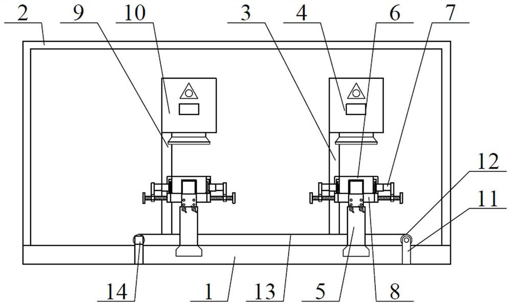
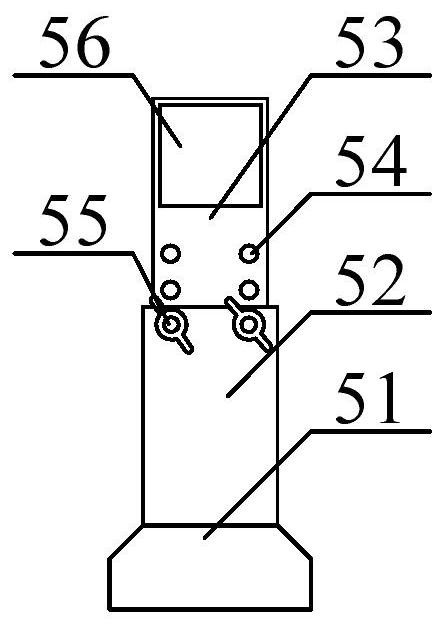
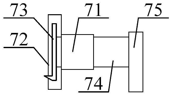
[0030] as attached figure 1 And attached Figure 4 As shown, a new type of bearing laser marking machine according to the present invention includes a horizontal bottom plate 1, an installation shell 2, a right side bracket 3, a right side laser marking machine 4, an adjustable rotating bracket structure 5, and a bearing storage frame 6. Bearing positioning and fixing frame structure 7, rotating clamping frame structure 8, left bracket 9, left laser marking machine 10, side plate 11, conveying roller 12, conveying belt 13 and conveying motor 14, the installation The casing 2 screws are installed on the outer upper part of the transverse base plate 1; the right side bracket 3 bolts are installed on the upper right side of the transverse base plate 1; the right side laser marking machine 4 bolts are installed on the upper side of the right side bracket 3 The adjustable rota...


PUM


Abstract

The invention discloses a novel bearing laser marking machine. The novel bearing laser marking machine comprises a transverse bottom plate, a mounting shell, a right bracket, a right laser marking machine body, adjustable rotary bracket structures, bearing storage frames, bearing positioning fixing frame structures, rotary clamping frame structures, a left bracket, a left laser marking machine body, side edge plates, conveying rolls, a conveying belt and a conveying motor, wherein the mounting shell is mounted at the upper part of the outer side of the transverse bottom plate through screws; the right bracket is mounted on the right side of the upper part of the transverse bottom plate through bolts; and the right laser marking machine body is installed on the upper side of the right bracket through bolts. Fixing nuts are welded to the lower parts of connecting plates respectively, so that each left-handed threaded rod and right-handed threaded rod can rotate in a fixing pipe by rotating rotating handles during use, then the connecting plates are driven to move left and right conveniently according to needs, and bearings are clamped through rectangular movable pipes by means of L-shaped clamping frames.

Description

technical field [0001] The invention belongs to the technical field of laser marking, in particular to a novel bearing laser marking machine. Background technique [0002] The DATAMATRIX two-dimensional barcode recognition technology is used in the former pair of bearing parts. Each set of bearings has a unique two-dimensional code and clear code, which records the bearing supplier, bearing code, production date, production line, product serial code, etc. Information, at present, the laser is used to mark the two-dimensional code on the large end face of the bearing, and the laser marks the clear code on the small end face of the bearing, and the two are mutually unified. [0003] However, the existing laser marking machines for bearings have the problems of not being able to turn over the work seat according to the requirements, inconveniently clamping the bearing and inconveniently positioning the clamping frame. [0004] Therefore, it is very necessary to invent a new be...

Claims


Application Information

Patent Timeline
IPC IPC(8): B23K26/362B23K26/70
CPCB23K26/362B23K26/702
Inventor 吴九一
Owner 张家港九霞激光设备有限公司
Learn More