
Efficient spiral extrusion structure suitable for 3D printer

A 3D printer and spiral technology, applied in the field of high-efficiency spiral extrusion structure, can solve problems such as limiting the printing speed and printing quality of 3D printers, increasing the complexity of the overall structure, affecting the extrusion and printing effects, and improving printing efficiency. and print performance, extend extrusion work time, and increase convenience

Pending Publication Date: 2020-09-25
湖北地创三维科技有限公司
View PDF1 Cites 2 Cited by
  • Summary
  • Abstract
  • Description
  • Claims
  • Application Information

AI Technical Summary

Problems solved by technology

[0002] At present, the commonly used extrusion structure of 3D printers using fused deposition modeling technology is single-gear or double-gear extrusion. Since the extrusion gear and consumables are close to linear contact, the extrusion contact area is small, the extrusion force is weak, and the extrusion gear It is easy to wear and tear, which greatly limits the improvement of the printing speed and printing quality of 3D printers. Although there is also a plan to improve the spur gear into a gear with U-shaped grooves, it does not fundamentally solve the problem due to extrusion. The small contact surface makes it difficult to extrude some materials and consumables;
[0003] A Chinese utility model patent with the notification number CN206598540U discloses a 3D printer extruder that adopts thread bite extrusion. By setting a threaded shaft next to the extrusion hole of the extruder body and driving the threaded shaft to rotate by a motor, the While the threads of the threaded shaft engage the consumables in the extrusion hole and rotate, they can drive the consumables to move axially along the extrusion hole for extrusion, which improves the extrusion effect to a certain extent; but this existing spiral extrusion structure is obviously It has more advantages, and it is not as popular as the gear extrusion structure in the industry. The main reasons are the following problems: First, it cannot take into account the balance of extrusion and the compactness and rationality of the structure. One motor drives a threaded shaft to rotate because one side of the consumable is affected. force, which will affect the stability of extrusion and cause insufficient extrusion power. If multiple external motors are used to drive multiple threaded shafts, or one external motor drives multiple threaded shafts through a complex transmission structure, both will Increase the complexity of the overall structure; second, long-term use causes the extrusion effect to decline. Although the existing spiral extrusion structure increases the extrusion contact surface with the consumables, because the structure is relatively closed, the temperature will rise after the bite friction High, and the increase of debris cannot be cleaned, which affects the extrusion effect; third, the spiral extrusion will drive the consumables to rotate during the extrusion process, affecting the extrusion and printing effects

Method used


Image

  • Efficient spiral extrusion structure suitable for 3D printer
  • Efficient spiral extrusion structure suitable for 3D printer
  • Efficient spiral extrusion structure suitable for 3D printer

Examples


Embodiment Construction

[0029] The present invention can be explained in detail by the following examples, and the purpose of disclosing the present invention is intended to protect all technical improvements within the scope of the present invention, and the present invention is not limited to the following examples; in the description of the present invention, it needs to be understood Yes, if there are orientations or positional relationships indicated by the terms "upper", "lower", "front", "rear", "left", "right", etc., they only correspond to the drawings of this application, for the convenience of describing this invention, without indicating or implying that the device or element referred to must have a particular orientation:

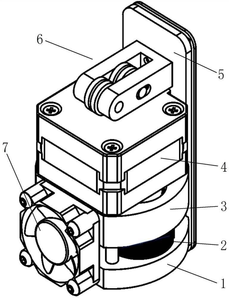
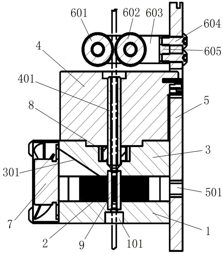
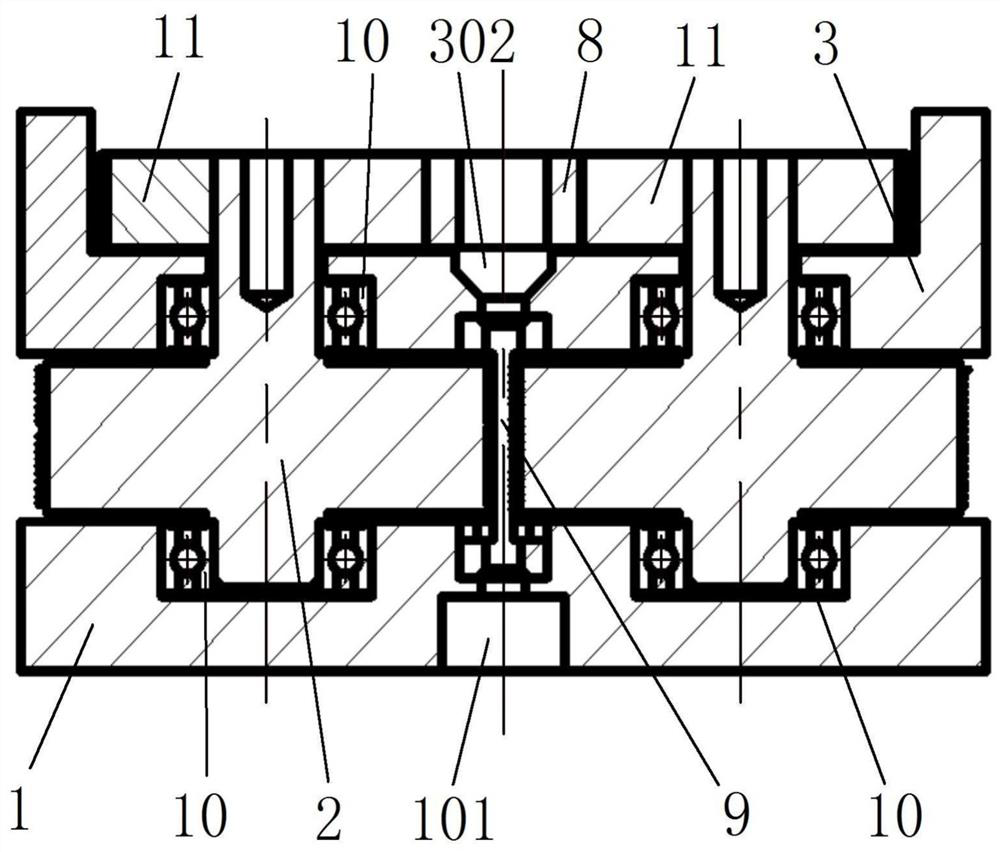
[0030] combined with Figure 1-9 The high-efficiency spiral extrusion structure suitable for 3D printers includes a hollow shaft motor 4, a threading pipe 9, and upper and lower corresponding upper and lower fixing seats 3 and 1, in order to ensure that the upper and ...


PUM


Abstract

The invention relates to an efficient spiral extrusion structure suitable for a 3D printer and relates to the field of 3D printer equipment. The efficient spiral extrusion structure comprises a hollowshaft type motor, a threading pipe, an upper fixing seat and a lower fixing seat, wherein the hollow shaft type motor is provided with a hollow rotating shaft, the two ends of the threading pipe areseparately mounted on the upper fixing seat and the lower fixing seat, two extrusion screws are symmetrically arranged outside the two sides of the threading pipe, and notches are formed in two corresponding side walls of the threading pipe; the upper and lower ends of the extrusion screws are rotatably connected with the upper fixing seat and the lower fixing seat, and the upper ends of the two extrusion screws are sleeved with a driven gear; a rotating shaft step hole is formed in the upper surface of the upper fixing seat, the lower end of the hollow rotating shaft is adapted to be insertedinto the rotating shaft step hole, and a driving gear is fixed on a shaft body of the lower portion of the hollow rotating shaft in a sleeving mode; a consumable limiting device is arranged above thehollow shaft type motor; and a cooling fan is mounted on the same sides of the upper fixing seat and the lower fixing seat. The spiral extrusion structure is small and reasonable in design, convenient to clean and maintain, and remarkably improves the extrusion effect of a spiral extrusion consumable.

Description

technical field [0001] The invention relates to the field of 3D printer equipment, in particular to a high-efficiency spiral extrusion structure suitable for 3D printers. Background technique [0002] At present, the commonly used extrusion structure of 3D printers using fused deposition modeling technology is single-gear or double-gear extrusion. Since the extrusion gear and consumables are close to linear contact, the extrusion contact area is small, the extrusion force is weak, and the extrusion gear It is easy to wear and tear, which greatly limits the improvement of the printing speed and printing quality of 3D printers. Although there is also a plan to improve the spur gear into a gear with U-shaped grooves, it does not fundamentally solve the problem due to extrusion. The small contact surface makes it difficult to extrude some materials and consumables; [0003] A Chinese utility model patent with the notification number CN206598540U discloses a 3D printer extruder ...

Claims


Application Information

Patent Timeline
Patent Type & Authority Applications(China)
IPC IPC(8): B29C64/112B29C64/118B29C64/20B29C64/227B29C64/30B29C64/307B33Y30/00B33Y40/00
CPCB33Y30/00B33Y40/00B29C64/112B29C64/118B29C64/20B29C64/227B29C64/30B29C64/307
Inventor 吴专郑乃博徐嘉琪刘辉林郭晶余煜陈春
Owner 湖北地创三维科技有限公司
Learn More