Rope coring drilling tool

A technology of core drilling tools and ropes, which is applied in the direction of extracting undisturbed core devices, earthwork drilling, surveying, etc., and can solve problems such as complex working conditions, unrecoverable bullet jams, and increased drilling pressure

Active Publication Date: 2020-09-25
EXPLORATION TECH RES INST OF CHINESE ACADEMY OF GEOLOGICAL SCI
View PDF5 Cites 6 Cited by
  • Summary
  • Abstract
  • Description
  • Claims
  • Application Information

AI Technical Summary

Problems solved by technology

However, existing wireline coring tools have certain defects in the coordination of internal and external assemblies and the positioning of internal assemblies, in-place notifications, core blockage alarms, single-action mechanisms, and core pipe check valves. The main defects are as follows: A few aspects: First, the cartridge positioning mechanism of the inner assembly adopts a single-point hinged method. When the core pipe is blocked, it is easy to cause the cartridge to be blocked, resulting in the failure of the cartridge to be recovered and the salvage failure of the inner pipe assembly. Second, the in-position reporting mechanism and the core plugging alarm mechanism of the wireline coring tool are set independently. Not only are there a large number of parts, but also the reliability of the in-position reporting and core plugging alarm prompts is poor. There are problems such as the phenomenon of single pipe during drilling and large core loss; thirdly, in the core pipe check valve mechanism, the steel ball is used to cooperate with the fixed valve seat. Small, the steel ball and the fixed ball seat are in a bonded state during surface core out operation, causing negative pressure inside the core tube, increasing the diffic

Method used


Image

  • Rope coring drilling tool
  • Rope coring drilling tool
  • Rope coring drilling tool

Examples


Embodiment Construction

[0064] The present invention will be further described below with reference to the accompanying drawings and specific embodiments.

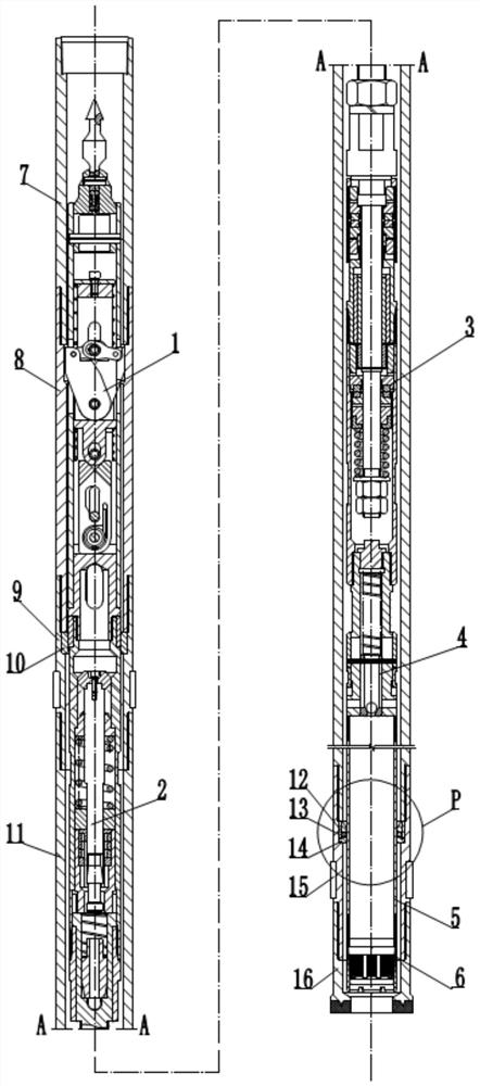
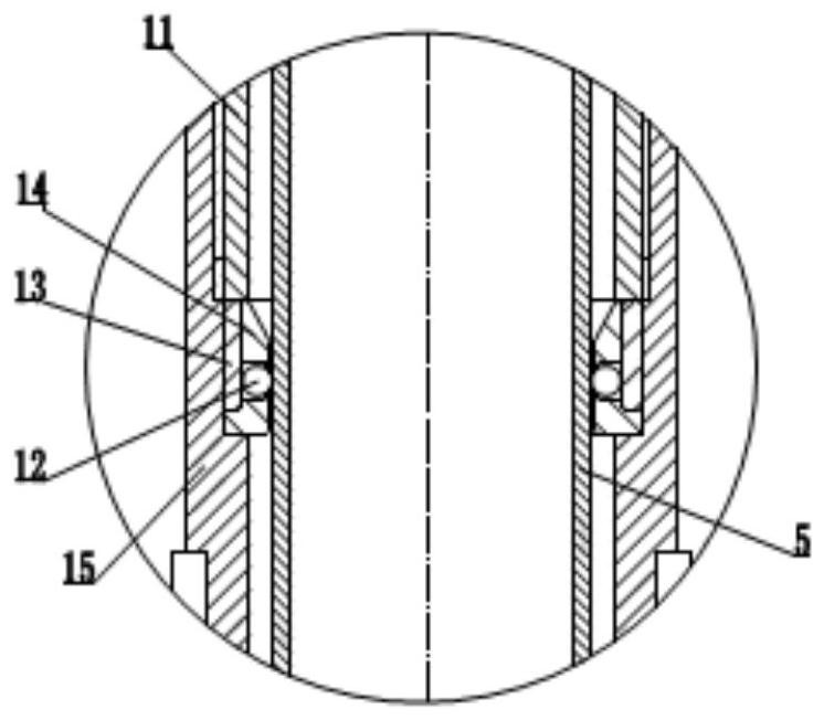
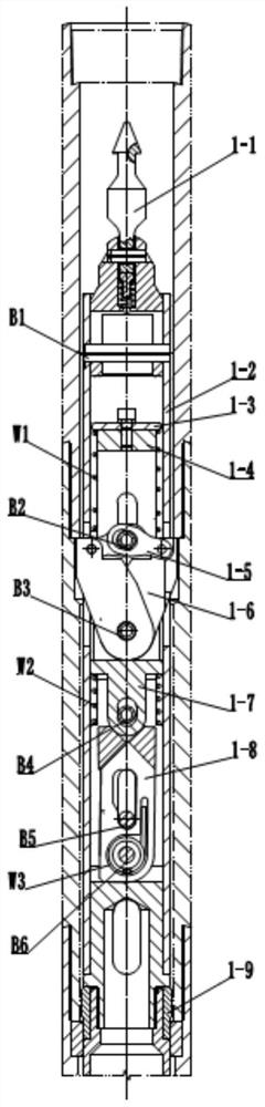
[0065] see figure 1 , figure 2 , The present invention provides a corded core drilling tool, which includes an outer tube assembly and an inner tube assembly; the inner tube assembly is sequentially provided with a clip positioning mechanism 1, an in-position notification and a core blockage alarm mechanism 2 from top to bottom , single-action mechanism 3, core one-way valve mechanism 4, core tube 5 and core breaking mechanism 6, the elastic card positioning mechanism 1 adopts a multi-point hinge, and the in-position notification and core blockage alarm mechanism 2 are integrated into one, so The single-action mechanism 3 adopts the matching structure of the upper and lower groups of PDC bearings and the TC bearing arranged in the middle. The core check valve mechanism 4 controls the opening and closing of the check valve through the cooperatio...


PUM


Abstract

The invention discloses a rope coring drilling tool. The rope coring drilling tool comprises an outer pipe assembly and an inner pipe assembly, wherein the inner pipe assembly is provided with an elastic clamping positioning mechanism, an in-place signaling and core blocking alarm mechanism, a single-acting mechanism, a core one-way valve mechanism, a core pipe and a core breaking mechanism, the elastic clamping positioning mechanism adopts a multi-point hinge manner, in-place signaling and a core blocking alarm mechanism are integrated into a whole, the single-acting mechanism adopts a matching structure of an upper PDC bearing, a lower PDC bearing and a TC bearing arranged in the middle, and the core one-way valve mechanism controls opening and closing of a one-way valve through cooperation of a steel ball and a liftable valve seat; and the outer pipe assembly is provided with an elastic clamping baffle, an elastic clamping chamber, an upper reamer, an outer pipe, a lower reamer anda drill bit, a ring seat is embedded in an annular groove formed between the lower end of the elastic clamping chamber and the inner side wall of the upper reamer, and a righting ring is embedded in an annular groove formed between the lower end of the outer pipe and the inner side wall of the lower reamer. According to the rope coring drilling tool, the coring drilling efficiency and the core taking quality can be improved, and the purpose of saving the drilling cost is achieved.

Description

technical field [0001] The invention relates to a wire rope coring drill, in particular to a wire rope coring drill suitable for extra-deep scientific drilling. Background technique [0002] In order to grasp the underground geological conditions, people usually use the method of drilling and coring to obtain real and reliable underground rock formation data. The wire rope coring method is widely used in various drilling engineering fields such as geological exploration, hydrogeology and engineering investigation due to its advantages of high drilling efficiency, low cost and few drilling accidents. serialization. [0003] Extra-deep scientific drilling is a scientific exploration activity to carry out geological research by coring and reusing obtained cores from extra-deep holes. The wire-line coring drilling process is also selected. Affected by the drilling depth and stratigraphic structure, the drilling conditions at the bottom of the hole will be very complicated dur...

Claims


Application Information

Patent Timeline
IPC IPC(8): E21B25/02E21B25/04E21B34/06
CPCE21B25/02E21B25/04E21B34/06E21B25/10E21B2200/06E21B34/14E21B47/00
Inventor 李鑫淼梁健李宽尹浩刘秀美
Owner EXPLORATION TECH RES INST OF CHINESE ACADEMY OF GEOLOGICAL SCI
Why Eureka
Try Eureka