Hydraulic anchor drill rig and three-working-position propelling beam thereof

A technology of advancing beam and three-station, applied in the fields of tunnel construction machinery and mining, can solve the problems of unmentioned angle error, heavy advancing beam, complicated operation, etc., and achieve the lifting rate, continuous rock drilling and anchoring process, and good economic benefits. Effect

Pending Publication Date: 2020-09-25
ZHEJIANG KAISHAN HEAVY IND CO LTD
View PDF9 Cites 7 Cited by
  • Summary
  • Abstract
  • Description
  • Claims
  • Application Information

AI Technical Summary

Problems solved by technology

[0006] 1) Although the drill-bolt switching rate has been improved to a certain extent compared with the original bolt support scheme, there is still room for improvement;
[0007] 2) For rock bolters using double rock drills, two sets of propulsion devices are often used, which makes the propulsion beam very heavy and complicated to operate
[0009] Although this patent document solves the above-mentioned technical problems, those skilled in the art find that there are still deficiencies during use; theoretically, after the drilling mechanism completes a positioning, as long as the swivel frame rotates at a specific angle, the subsequent bolting operations and The anchoring operation does not need to be positioned again, but this is not the case in the actual operation process. For example, the entire drilling rig mechanism is in a state of vibration during drilling operations, and this will obviously cause a certain displacement of the drilling rig, so the subsequent rotation frame There is also a certain deviation after rotating a specific angle. In addition, how to ensure that the rotating frame rotates at a specific angle and the rotation angle error is small enough is not mentioned in the above patent documents

Method used


Image

  • Hydraulic anchor drill rig and three-working-position propelling beam thereof
  • Hydraulic anchor drill rig and three-working-position propelling beam thereof
  • Hydraulic anchor drill rig and three-working-position propelling beam thereof

Examples


Embodiment 1

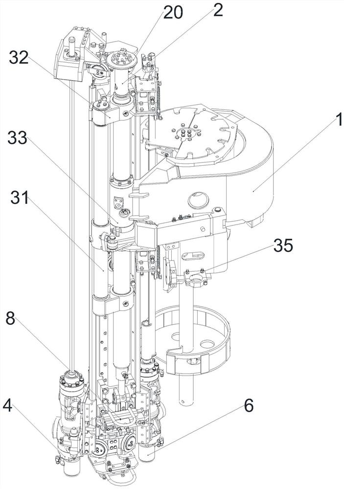
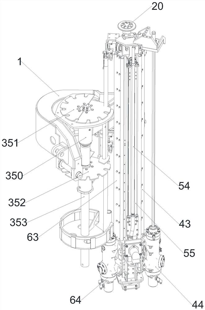
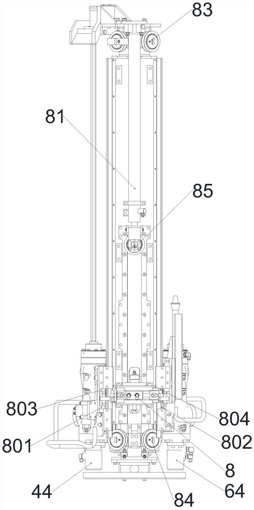
[0051] A hydraulic rock bolter, comprising an engineering chassis, a working arm, such as Figure 1-3 The three-station propulsion beam, electrical device, hydraulic device and cab are shown; among them, the engineering chassis is used to provide support for the whole vehicle to ensure the rigidity and strength of the whole vehicle, and the front lateral telescopic form of the legs of the engineering chassis can ensure The stability of the whole vehicle, the electrical device and hydraulic device are used to ensure the normal operation of the three-station propulsion beam and the working arm, and the cab is used to accommodate the driver and the driver manipulates the working arm and the three-station propulsion beam to complete the underground Support work; the three-station propulsion beam is installed on the working arm and adjusted to the vertical state through the working arm;

[0052] In this embodiment, the three-station propelling beam includes a bracket 1 installed on...


PUM


Abstract

The invention discloses a hydraulic anchor drill rig and a three-working-position propelling beam thereof. The three-working-position propelling beam comprises a fixing beam, a rotating beam, a drilling device, an anchor rod device and an anchoring device; the rotating beam comprises a pushing rod, a sleeve and a plurality of connecting pieces; the sleeve is mounted on the fixing beam in a sleeving manner and can rotate relative to the fixing beam; the drilling device and the anchor rod device are respectively positioned on the two sides of the anchoring device; the pushing rod is driven by aswitching oil cylinder to rotate with the fixing beam as a central shaft; and moreover, in the drilling operation, the anchoring operation, the anchor rod operation and the rotating process of the rotating beam, the top end of the fixing beam always abuts against a tunnel roof needing to be anchored to be fixed. Through the technical scheme, the switching speed is greatly increased, and moreover,the angle accuracy and the locating accuracy in the switching process can also be guaranteed; and meanwhile, the whole vehicle cost can also be effectively reduced, and the three-working-position propelling beam is beneficial for further popularization of underground support mechanization.

Description

technical field [0001] The invention relates to the technical field of mine and tunnel engineering machinery, in particular to a hydraulic bolter drilling vehicle and a three-station propelling beam thereof. Background technique [0002] Underground support (roadway support) is mainly used to ease and reduce the movement of surrounding rock, so that the section of the roadway will not be excessively reduced, and at the same time prevent the scattered and damaged surrounding rock from caving; usually, in order to make the roadway support adjust and control Playing an active role in the deformation process of the surrounding rock, the support should be installed before the surrounding rock becomes loose and damaged, so that the support can play a bearing role together with the surrounding rock when the surrounding rock still maintains self-supporting force. [0003] Take bolt support as an example; in the process of bolt support, it is necessary to drill the bolt hole first, a...

Claims


Application Information

Patent Timeline
Patent Type & Authority Applications(China)
IPC IPC(8): E21D20/00E21D20/02E21B15/00
CPCE21B15/003E21D20/003E21D20/025
Inventor 徐雪锋杜标高强胜郑晓辉夏剑辉
Owner ZHEJIANG KAISHAN HEAVY IND CO LTD
Why Eureka
Try Eureka