

Electrolytic copper foil drying device
A technology of electrolytic copper foil and drying device, which is applied in the direction of drying, drying machine, drying gas arrangement, etc., can solve the problems of inconvenient copper foil surface water stain drying, secondary corrosion and oxidation, etc., to prevent secondary Rust oxidation, improvement effect, drying effect is obvious
- Summary
- Abstract
- Description
- Claims
- Application Information
AI Technical Summary
Problems solved by technology
Method used
Image

Examples
Embodiment 1
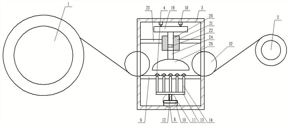
[0028] refer to Figure 1-4 , the present invention provides a drying device for electrolytic copper foil, which includes an unwinding roller 1 and a winding roller 2, and an electrolytic copper foil (not shown in the figure) is wound between the unwinding roller 1 and the winding roller 2. The winding roller 2 pulls the electrolytic copper foil to rewind, and drives the unwinding roller 1 to unwind. A box body 3 is provided between the unwinding roller 1 and the winding roller 2, and a guiding mechanism is arranged inside the box body 3. The bottom of the guide mechanism is provided with an air intake mechanism, the top of the guide mechanism is provided with a waste heat treatment mechanism, one side of the guide mechanism is provided with a driving mechanism, and the guide mechanism is provided with a friction mechanism;
[0029] The friction mechanism includes several rotating rollers 4 arranged on the guiding mechanism. The driving mechanism drives the rotating rollers 4 ...
Embodiment 2
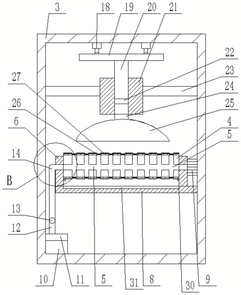
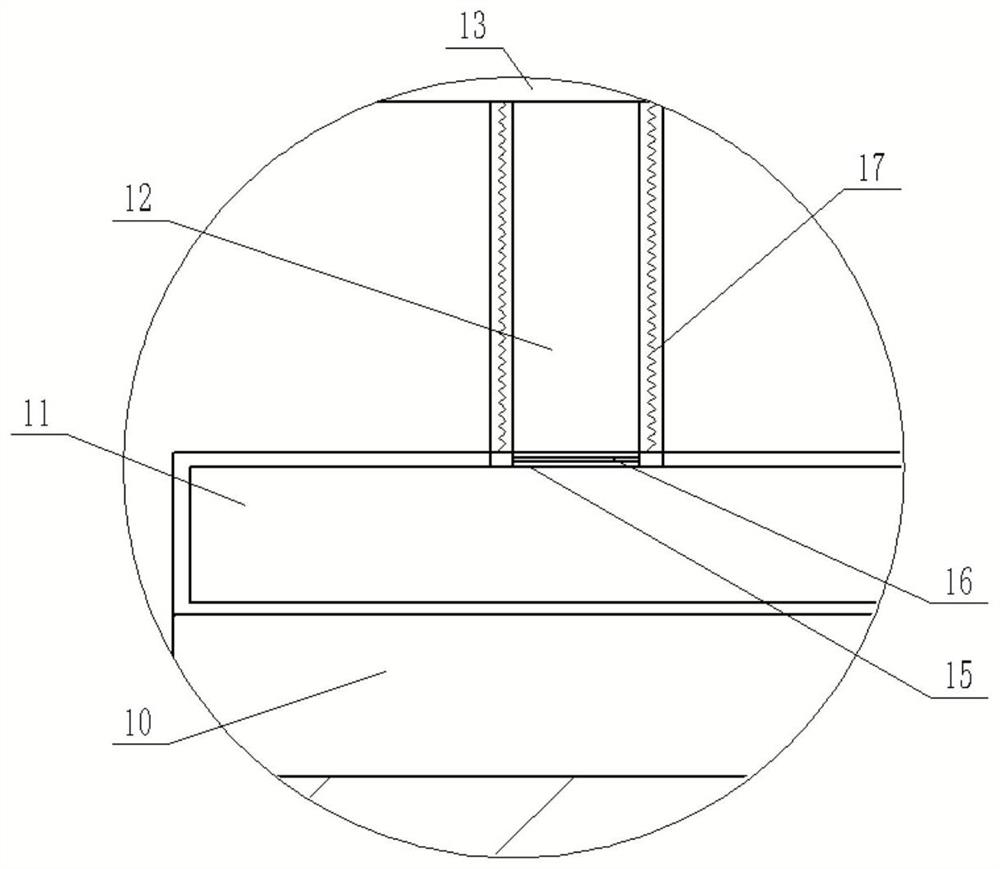
[0041] refer to Figure 5-7 , the two ends of the air collecting pipe 13 are connected with extension pipes respectively, and the two ends of the two extension pipes 33 are respectively connected with two conduits 34, the conduits 34 are perpendicular to the extension pipes 33, and the conduits 34 A pressurized nozzle 35 is fixed on the top, and the angle between the injection directions of the two pressurized nozzles 35 is not more than 180°. One side of the arc-shaped cover 25 is provided with a transition opening 36, which is an arc The pressurized nozzle 35 faces the transition opening 36, and a part of the hot air in the air collecting pipe 13 enters the pressurized nozzle 35 through the extension pipe 33 and the conduit 34, and the hot air is pressurized to the transition through the pressurized nozzle 35. Opening 36 sprays, and when push rod 20 draws air, part hot air flows to the junction of air outlet pipe 24 and arc cover 25, and the part below arc cover 25 is equiva...
PUM
 Abstract
Description
Claims
Application Information