Flexible display panel and preparation method thereof, display device and display module

A flexible display and panel technology, which is applied in the field of flexible display panels and the preparation of flexible display panels, and display modules, can solve the problems of poor lamination, easy cracks, and easy wrinkles, etc., to reduce lamination cracks and edge areas Effect of wrinkling, reducing fit stress and strain

Active Publication Date: 2020-09-25
BOE TECH GRP CO LTD +1
View PDF21 Cites 13 Cited by
  • Summary
  • Abstract
  • Description
  • Claims
  • Application Information

AI Technical Summary

Problems solved by technology

The edge areas of the four corners of the screen are subject to large tangential compressive stress, which is prone to wrinkles
Moreover, due to the design of the mechanism equipment and the flexible display panel, the profiling of the flexible display is often insufficient when the four sides of the OLED flexible display are curved, and the four corners of the flexible display will be warped, resulting in the flexible display and the cover. Pre-contact occurs, that is, the edge of the flexible display is in contact with the cover first, and then the inside is in contact, forming air bubbles
In this way, after bonding and defoaming, cracks are prone to occur, resulting in poor bonding.

Method used


Image

  • Flexible display panel and preparation method thereof, display device and display module
  • Flexible display panel and preparation method thereof, display device and display module
  • Flexible display panel and preparation method thereof, display device and display module

Examples


Embodiment Construction

[0076] Example embodiments will now be described more fully with reference to the accompanying drawings. Example embodiments may, however, be embodied in many forms and should not be construed as limited to the embodiments set forth herein; rather, these embodiments are provided so that this disclosure will be thorough and complete, and will fully convey the concept of example embodiments to those skilled in the art. The same reference numerals in the drawings denote the same or similar structures, and thus their detailed descriptions will be omitted.

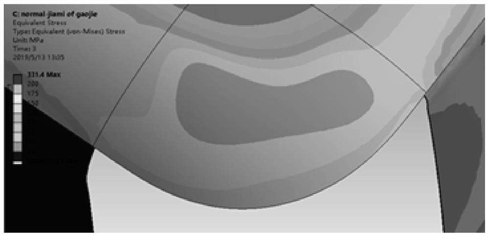
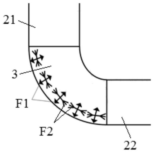
[0077] refer to figure 1 The schematic diagram of the stress distribution simulation of the corner bending area 3 after the flexible display panel in the related art is shown in the related art shows that the maximum tensile stress is concentrated in the middle area of ​​the corner bending area 3 of the flexible display panel. refer to figure 2 The schematic diagram of force analysis in the middle of the corner bending area...


PUM


Abstract

The invention relates to the technical field of display, and provides a flexible display panel and a preparation method thereof, a display device and a display module. The flexible display panel comprises a plane area, a first bending area, a second bending area and a corner bending area, the first bending area is connected to the first edge of the plane area in the first direction, the second bending area is connected to the second edge of the plane area in the second direction, and a set angle is formed between the second direction and the first direction; a corner bending area is connectedto the corner of the plane area; a corner bending area is arranged on the base and connected between the first bending area and the second bending area, the corner bending area is provided with a plurality of first hole sets, after the corner bending area is bent, the width of the first hole set located in the middle of the corner bending area is increased, and the width of the first hole set located in the edge area of the corner bending area is decreased. Tensile strain and compressive strain are absorbed through the first hole set, and attaching cracks and edge area wrinkles of the flexibledisplay panel are reduced. No bubbles can be generated.

Description

technical field [0001] The present invention relates to the field of display technology, in particular to a flexible display panel and a method for preparing the flexible display panel, a display device including the flexible display panel, and a display module including the flexible display panel. Background technique [0002] With the rapid development of display technology, the trend of the aesthetics and lightness of electronic products has gradually emerged. OLED (Organiclight-Emitting Diode, organic light emitting diode) Flexible display surface-fitting also develops rapidly. With the maturation of OLED flexible display two-sided curved bonding process, OLED flexible display four-sided curved bonding is increasingly favored by panel manufacturers and mobile phone manufacturers. [0003] However, a technical difficulty in the four-sided curved bonding of OLED flexible displays is corner bonding. As the depth of the OLED flexible display entering the corner arc of the c...

Claims


Application Information

Patent Timeline
Patent Type & Authority Applications(China)
IPC IPC(8): G09F9/30
CPCG09F9/301Y02E10/549G06F1/1652G06F1/1637G09G3/035G09G2300/04
Inventor 王亚明陈立强赵东东王作家刘雪燕李旭
Owner BOE TECH GRP CO LTD
Why Eureka
Try Eureka