Data room temperature patrol robot arranged on room ceiling and method

A technology for inspection robots and data computer rooms, applied in the directions of manipulators, manufacturing tools, etc., can solve the problems of large system space, complicated installation process, and inability to cover the computer room space.

Pending Publication Date: 2020-09-29
NANJING UNIV OF TECH
View PDF0 Cites 1 Cited by
  • Summary
  • Abstract
  • Description
  • Claims
  • Application Information

AI Technical Summary

Problems solved by technology

[0003] In recent years, the research on the temperature detection technology of the data center has made great progress, and related technologies have also emerged for the practical application of the temperature detection of the data center. The patent CN2019103263317 proposes a data center temperature detection system and its detection method. The patent The detection method comprehensively utilizes optical fiber Raman scattering effect and optical time domain reflectance measurement technology to measure the spatial temperature distribution along the optical fiber in real time, and can realize real-time and accurate temperature information collection for any specified measurement point. Multiple detection devices are installed. The installation process is complicated and the system takes up a lot of space; the patent CN2017216698370 proposes a precise monitoring system for the temperature field of a data center. The patent is to install temperature sensors at the air-conditioning air inlet and air-conditioning air outlet of each server cabinet respectively. The number is too large and difficult to control, and the detection points only cover the air-conditioning air inlet and outlet of the server cabinet, and cannot cover the entire computer room space

Method used


Image

  • Data room temperature patrol robot arranged on room ceiling and method
  • Data room temperature patrol robot arranged on room ceiling and method

Examples


Embodiment Construction

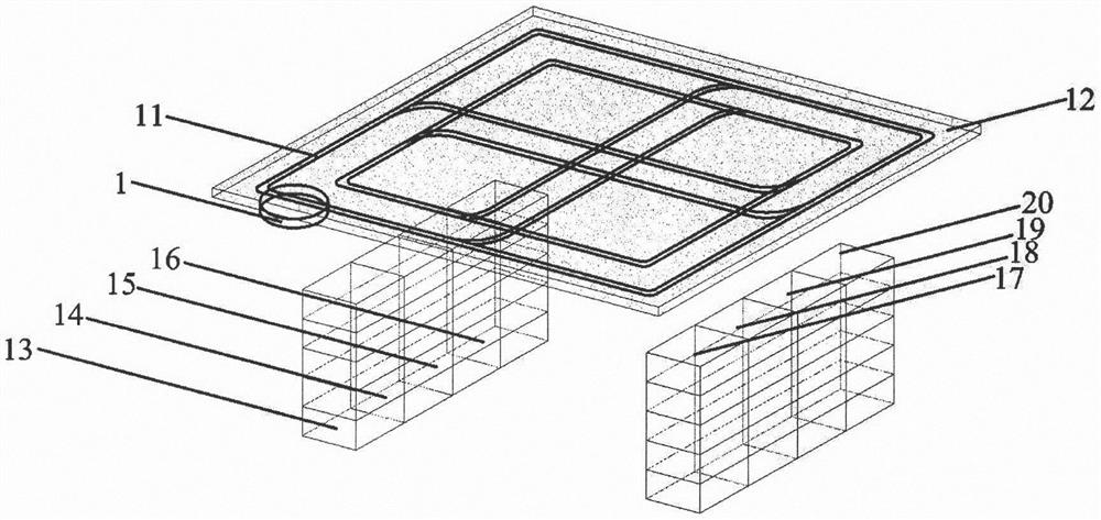
[0025] Such as figure 1 As shown, a data room temperature inspection robot arranged on the ceiling of the machine room mainly includes: 1. Robot body, 11. Magnetic guide rail, 12. Ceiling, 13. First cabinet, 14. Second cabinet, 15. Third Cabinet, 16. the fourth cabinet, 17. the fifth cabinet, 18. the sixth cabinet, 19. the seventh cabinet, 20. the eighth cabinet.

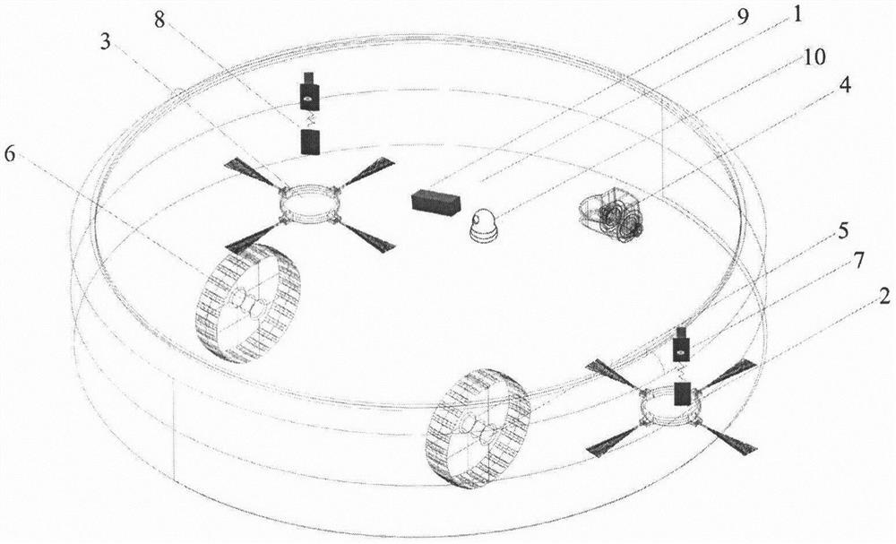
[0026] Such as figure 2As shown, the first robot hair brush 2 and the second robot hair brush 3 are respectively located on both sides of the front of the bottom of the robot body 1, the robot universal wheel 4 is located at the front of the bottom of the robot body 1, and the first robot hair brush 2 and the second robot hair brush The brushes 3 are respectively located on both sides of the rear of the universal wheel 4 of the robot, and the first robot power wheel 5 and the second robot power wheel 6 are respectively located on both sides of the rear of the bottom of the robot body 1, and are respectively locate...


PUM


Abstract

The invention discloses a data room temperature patrol robot arranged on a room ceiling and a method and belongs to the field of data room thermal environment detection. Through the data room temperature patrol robot arranged on the room ceiling and the method, the problems that space temperature of a data room is difficult to monitor, safety of the top of a cabinet cannot be monitored, installation space in the room is narrow, and dust deposition on the ceiling is difficult to remove are solved. The data room temperature patrol robot mainly comprises a robot body (1), a first robot brush (2),a robot universal wheel (4), a first robot power wheel (5), first extensible spring temperature sensors (7), an infrared temperature sensor (9), a camera (10), a magnetic attraction guide rail (11),the ceiling (12), the first cabinet (13) and the like. The extensible temperature sensors are installed on the two sides of the robot to measure temperature distribution in all positions of the room and are combined with the infrared temperature sensor to measure temperature distribution of the top of the cabinet, safety monitoring of the room is conducted by the camera, the robot moves through the magnetic attraction guide rail installed on the cabinet ceiling, and installation space is saved.

Description

technical field [0001] The invention relates to a data computer room temperature inspection robot and method arranged on the ceiling of the computer room, and belongs to the field of thermal environment detection of the data computer room. Background technique [0002] The server density in the data center computer room is extremely high, and high-density equipment will generate a lot of heat, which is prone to overheating. Overheated temperature not only greatly reduces the service life of the equipment, when the temperature reaches 90% of the limit value, the server will automatically shut down to prevent serious losses, and such automatic shutdown will also lose important information. This requires real-time detection and analysis of the data room temperature field, especially the cabinet server temperature. Under no circumstances are devices, such as servers, allowed to operate outside their operating temperature range. For local overheating areas, small refrigeration ...

Claims


Application Information

Patent Timeline
Patent Type & Authority Applications(China)
IPC IPC(8): B25J5/02B25J11/00B25J19/02
CPCB25J5/02B25J11/00B25J11/0085B25J19/02
Inventor 许鑫洁王瑜高阳成峰刘金祥
Owner NANJING UNIV OF TECH
Why Eureka
Try Eureka