A hydraulic mount structure
A technology of hydraulic mount and liquid cavity, which is applied in power plant, jet propulsion device, internal combustion propulsion device, etc., can solve the problems of slow response speed of vibration reduction, poor sealing effect, poor vibration reduction effect, etc. The possibility of liquid leakage is low, and the effect of improving the qualified rate of liquid sealing
- Summary
- Abstract
- Description
- Claims
- Application Information
AI Technical Summary
Problems solved by technology
Method used
Image
Examples
Embodiment 1
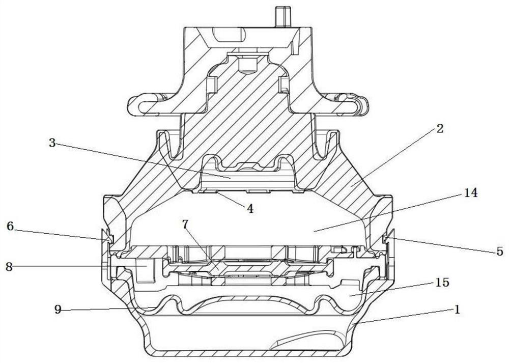
[0025] Such as figure 1 As shown, a hydraulic suspension structure, including the base plate bracket 1, the main spring rubber 2, the upper liquid chamber 14 and the lower liquid chamber 15, the main spring rubber 1, the upper liquid chamber 14 and the lower liquid chamber 15 are arranged in sequence from top to bottom , the inside of the main spring rubber 2 includes a main spring inner frame 3 communicating with the upper liquid chamber, and the main spring inner frame 3 is provided with a convex strip 4 adjacent to the upper liquid chamber 14, and the convex strip 4 is circumferentially arranged on the inner side wall of the main spring rubber 2 Above, the bottom of the main spring rubber 2 is provided with a first annular groove 5, the first annular groove 5 is arranged on the outer wall of the main spring rubber 2, and the upper edge of the bottom plate bracket 1 is provided with a groove that matches the first annular groove 5. The ring buckle 6 is an interference fit wi...
Embodiment 2
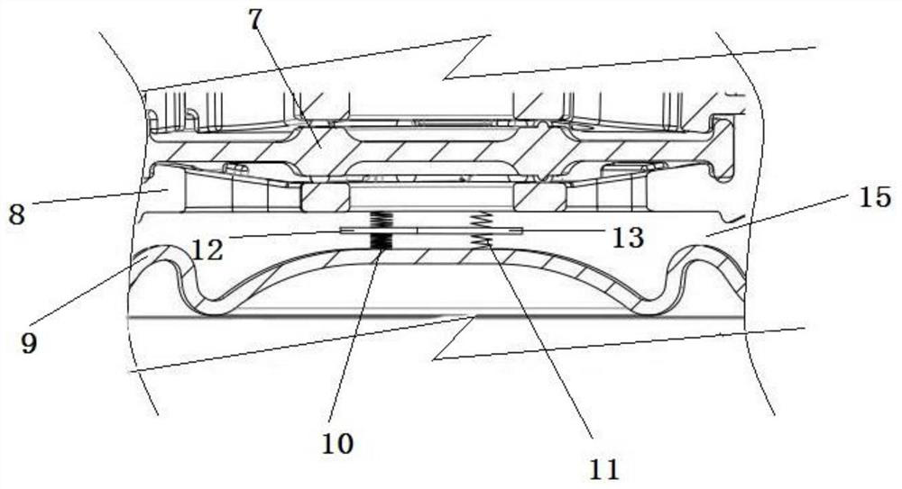
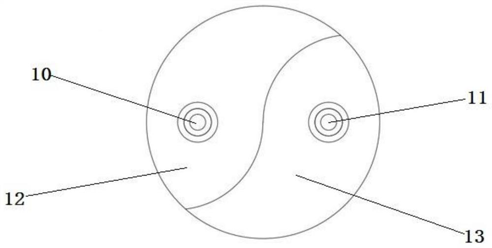
[0028] Based on Example 1, such as figure 2 , image 3 As shown, the bottom of the lower liquid chamber is a bowl-mounted lower diaphragm 9, the lower diaphragm 9 and the decoupling plate 8 form a lower liquid chamber, and a vertical arrangement is arranged between the lower diaphragm 9 and the decoupling membrane 8. The rotary spring is provided with a horizontal partition in the middle of the rotary spring. When the rotary spring is compressed, the partition rotates around the spring. The rotating springs include left rotating springs 10 and right rotating springs 11 arranged side by side. The left rotating springs 10 and right rotating springs 11 have different elastic coefficients. 12. The partition provided in the middle of the right rotation spring 11 is the second partition 13, and the cross-sections of the first partition 12 and the second partition 13 are respectively in the shape of a yin and yang fish. Both the first partition 12 and the second partition 13 are m...
PUM
 Abstract
Description
Claims
Application Information
 - R&D
- Intellectual Property
- Life Sciences
- Materials
- Tech Scout
- Unparalleled Data Quality
- Higher Quality Content
- 60% Fewer Hallucinations
Browse by: Latest US Patents, China's latest patents, Technical Efficacy Thesaurus, Application Domain, Technology Topic, Popular Technical Reports.
© 2025 PatSnap. All rights reserved.Legal|Privacy policy|Modern Slavery Act Transparency Statement|Sitemap|About US| Contact US: help@patsnap.com


