High-low temperature test system of optical module

A test system, high and low temperature technology, applied in thermometers, measuring devices, measuring heat, etc., can solve problems such as low efficiency, inability to prevent fools, and increased manual workload, so as to increase the rate of heating and cooling, reduce equipment costs, and reduce The effect of production risk

Inactive Publication Date: 2020-09-29
WUHAN HUAGONG GENUINE OPTICS TECH
View PDF16 Cites 0 Cited by
  • Summary
  • Abstract
  • Description
  • Claims
  • Application Information

AI Technical Summary

Problems solved by technology

However, both of the above methods have certain disadvantages
[0003] Among them, the manual moving method increases the manual workload, makes the employees prone to fatigue, and has the risk of bumping into products and fixtures by mistake; at the same time, it is inefficient; the cantilever method will increase the cost and volume of the equipment on the one hand, and on the other hand requires employees to work independently. After aligning the position, the operating temperature control parts will drop, and it is impossible to perform fool-proof treatment for the situation where the position is not aligned, and there is a certain production risk
In addition, in the existing test process, most of the modules are placed in a test area space to cool or heat up the space as a whole. Only when the entire space reaches the set temperature can the module be effectively heated and heated. Cools down, is inefficient and wastes energy

Method used


Image

  • High-low temperature test system of optical module
  • High-low temperature test system of optical module
  • High-low temperature test system of optical module

Examples


Embodiment Construction

[0023] The following will clearly and completely describe the technical solutions in the embodiments of the present invention with reference to the accompanying drawings in the embodiments of the present invention. Obviously, the described embodiments are only some, not all, embodiments of the present invention. Based on the embodiments of the present invention, all other embodiments obtained by persons of ordinary skill in the art without making creative efforts belong to the protection scope of the present invention.

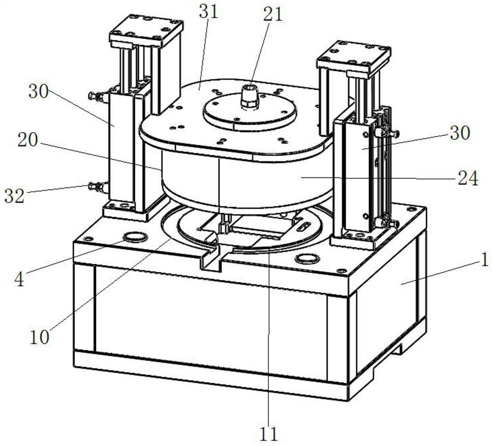
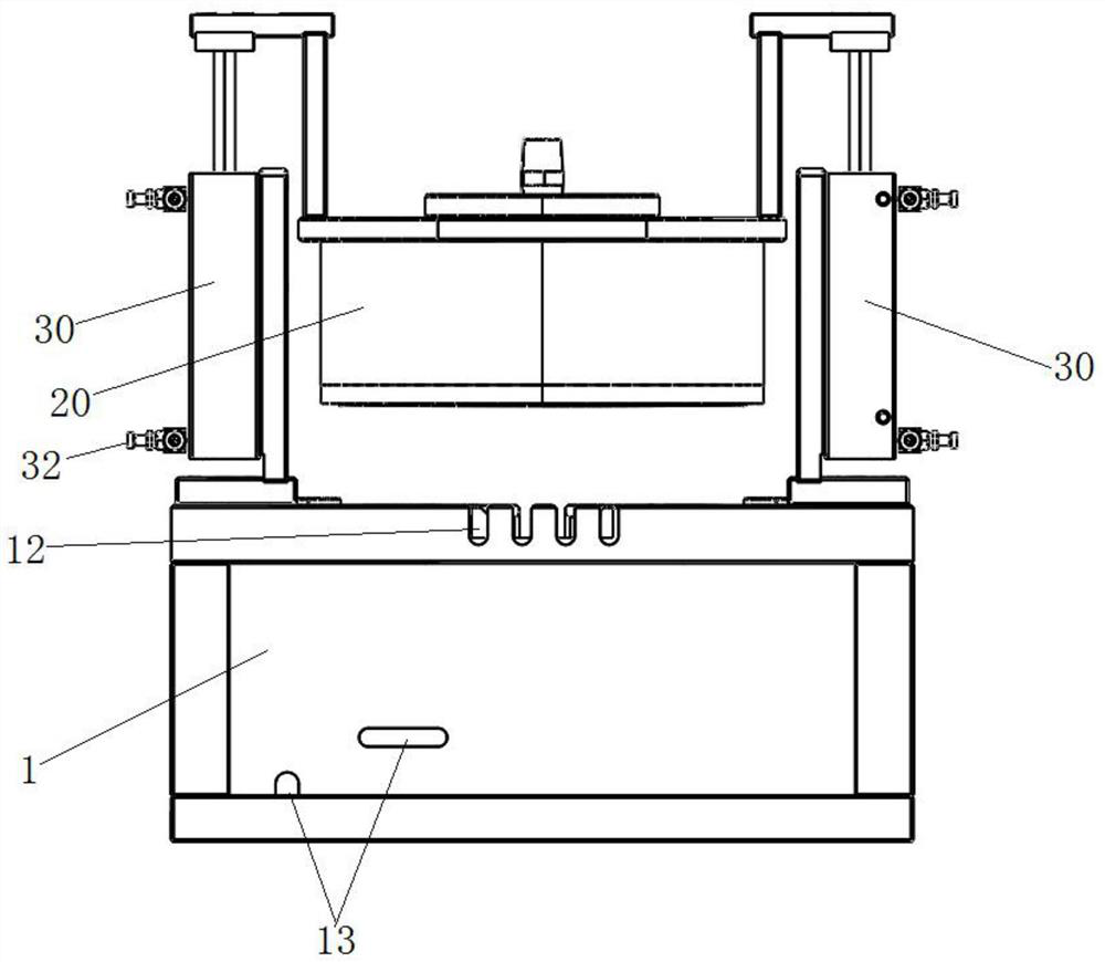
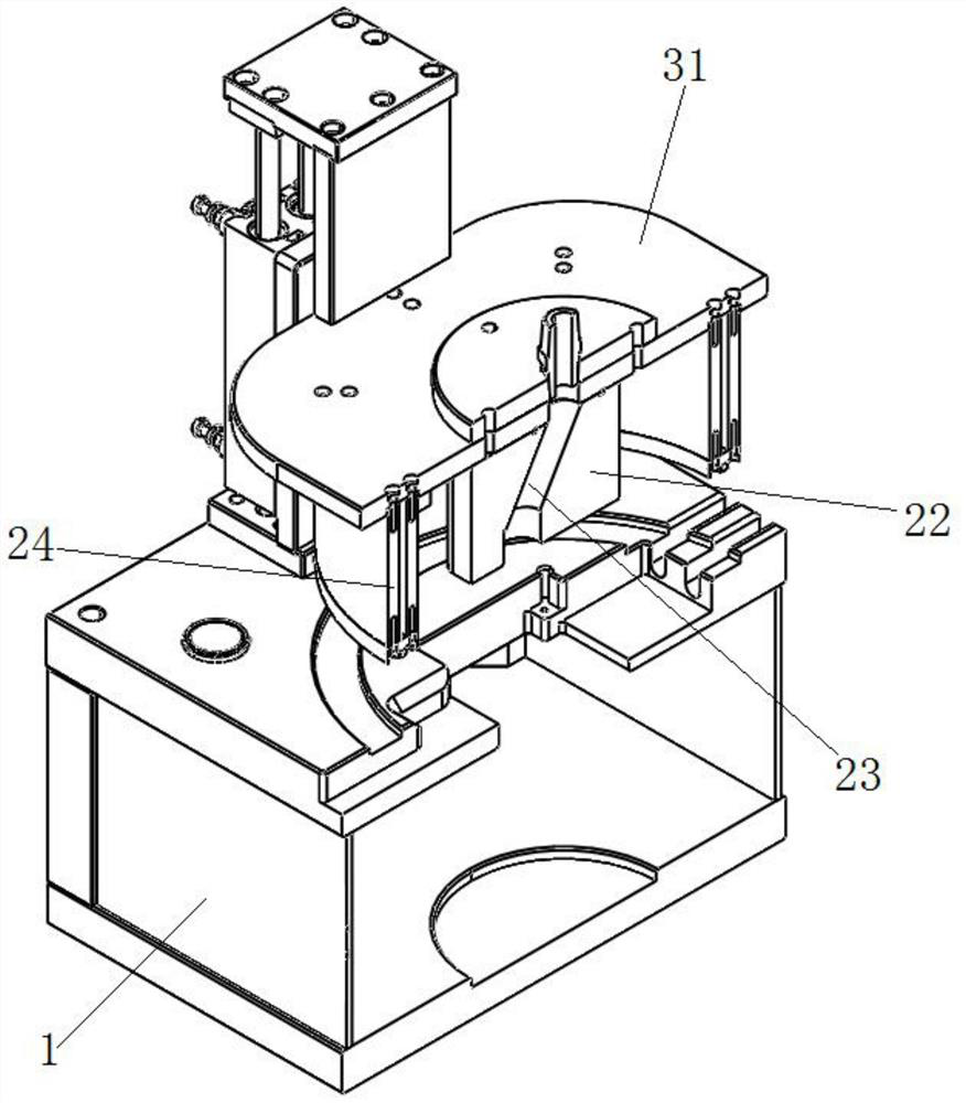
[0024] see figure 1 , figure 2 and image 3 , the embodiment of the present invention provides a high and low temperature test system for an optical module, including a base 1, a product test area 10 for placing the optical module to be tested, and a test component for providing high and low test temperatures for the optical module to be tested And a driving mechanism for driving the test assembly close to or away from the product to-be-tested area 10, the ...


PUM


Abstract

The invention relates to the technical field of optical communication module high and low temperature testing, and provides a high and low temperature test system of an optical module. The system comprises a base, a product to-be-tested area for placing a to-be-tested optical module, a testing assembly for providing high and low testing temperatures for the to-be-tested optical module, and a driving mechanism for driving the testing assembly to be close to or far away from the product to-be-tested area, wherein the to-be-tested area of the product is arranged on the base, the testing assemblyis provided with a cover body used for covering the to-be-tested area of the product so as to seal the to-be-tested optical module on the base, and the cover body is provided with an air outlet connected with an external temperature controller. The motion position of the testing assembly is fixed relative to the testing plate and the optical module, manual alignment is not needed, the position deviation risk is avoided, the production risk is reduced, and the working efficiency is also improved through mechanical motion; due to the design of the gas flow guide block, cold and hot gas is directly guided to the to-be-tested optical module, the heating and cooling rate of the to-be-tested optical module can be effectively improved, and the test efficiency is improved.

Description

technical field [0001] The invention relates to the technical field of high and low temperature testing of optical communication modules, in particular to a high and low temperature testing system for optical modules. Background technique [0002] During the high and low temperature test of the optical communication module, it is necessary to continuously take and put the module from the test fixture, and this process needs to remove the temperature control part first. The traditional method of removing the temperature control part is manually moving or moving the temperature control part up and down in a cantilever manner. However, there are certain defects in the above two methods. [0003] Among them, the manual moving method increases the manual workload, makes the employees prone to fatigue, and has the risk of bumping into products and fixtures by mistake; at the same time, it is inefficient; the cantilever method will increase the cost and volume of the equipment on ...

Claims


Application Information

Patent Timeline
Patent Type & Authority Applications(China)
IPC IPC(8): G01K13/00G01K1/14
CPCG01K13/00G01K1/14
Inventor 陈绍望鲁小义马威
Owner WUHAN HUAGONG GENUINE OPTICS TECH
Why Eureka
Try Eureka