Seabed sand wave long-term observation device and method applied to internal wave development area

A technology of observation device and development area, which is applied in the field of long-term observation devices for seabed sand waves, can solve the problems of difficulty in completing sampling work, consumes large electric energy, and has a long period, and achieves the effects of reducing observation costs and increasing endurance.

Active Publication Date: 2020-09-29
OCEAN UNIV OF CHINA
View PDF9 Cites 5 Cited by
  • Summary
  • Abstract
  • Description
  • Claims
  • Application Information

AI Technical Summary

Problems solved by technology

[0004] However, due to the high penetration intensity of the sandy seabed, the sampling column in the existing gravity sampling device is difficult to penetrate, so it is difficult to complete the sampling work by gravity sampling; and the box sampler and the clam sampler cannot collect the inside of the seabed When taking samples from the surface of the seabed, due to the effect of sand and gravel, it is difficult to completely close, and sand leakage often occurs. At present, there is no sampling device that can effectively obtain the profile information of the sediment inside the sandy seabed, and the above-mentioned patent does not solve the problem. This problem also leads to the lack

Method used


Image

  • Seabed sand wave long-term observation device and method applied to internal wave development area
  • Seabed sand wave long-term observation device and method applied to internal wave development area
  • Seabed sand wave long-term observation device and method applied to internal wave development area

Examples


Example Embodiment

[0052] In order to make the above-mentioned objects, features and advantages of the present invention more obvious and understandable, the specific embodiments of the present invention will be described in detail below with reference to the accompanying drawings.

[0053] In the following description, specific details are set forth in order to fully understand the present invention. However, the present invention can be implemented in many other ways different from those described herein, and those skilled in the art can make similar extensions without departing from the connotation of the present invention. Therefore, the present invention is not limited by the specific embodiments disclosed below.

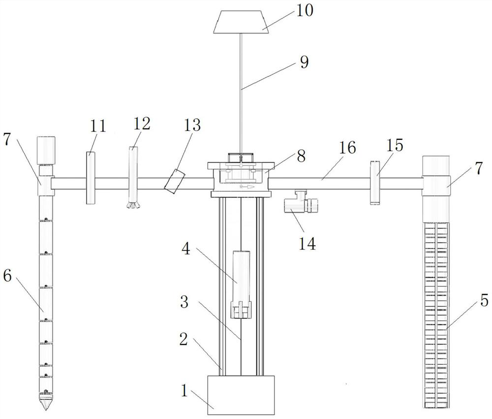
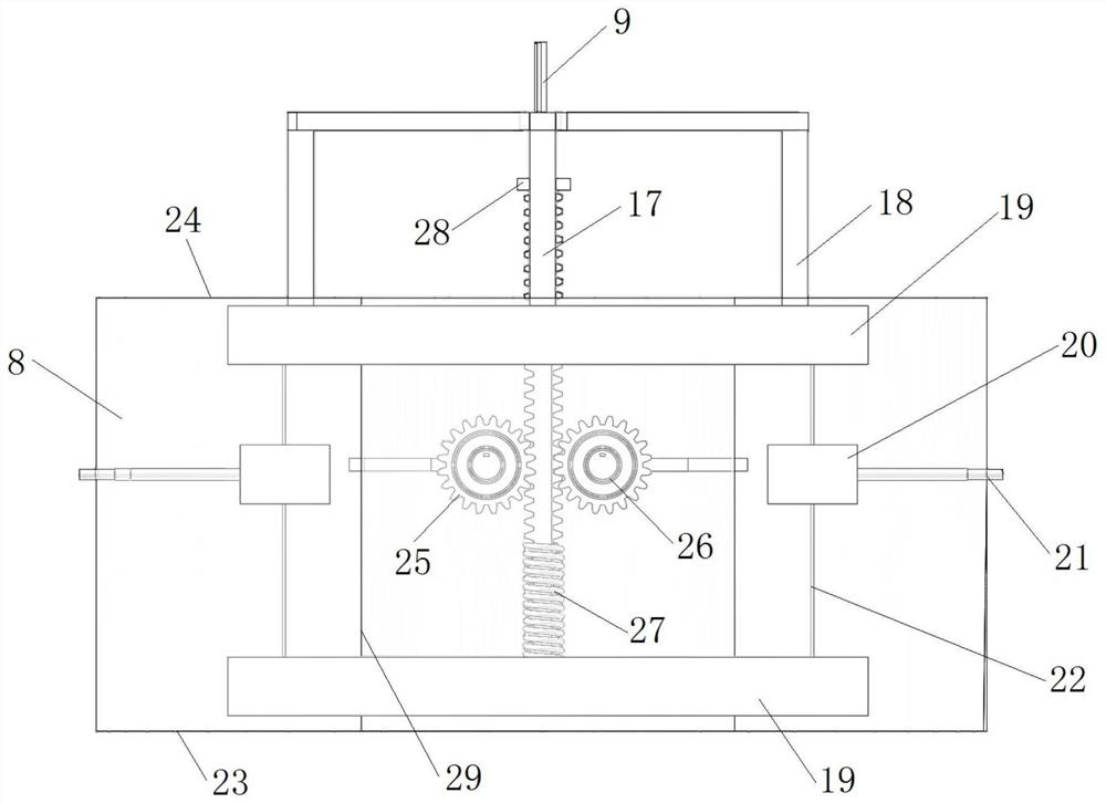
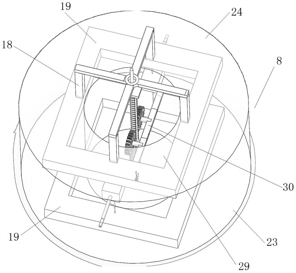
[0054] Such as figure 1 As shown, the submarine sand wave long-term observation device applied to the internal wave development area of ​​the present invention includes a submarine target 10, a supporting mechanism, a multifunctional observation rod 6, a sandy sediment sampling rod 5 ...


PUM


Abstract

The invention relates to the field of seabed observation, and particularly relates to a seabed sand wave long-term observation device and method applied to an internal wave development area. A supporting mechanism is in the shape of a balance and comprises a gravity anchor, hexagonal rods, an annular instrument control cabin and supporting rods, the gravity anchor is positioned at the bottom of the whole device, the gravity anchor is connected with the annular instrument control cabin above the gravity anchor through a plurality of hexagonal rods, an internal wave energy power generation mechanism is arranged in the annular instrument control cabin, two supporting rods are symmetrically fixed on the outer side of the annular instrument control cabin, one supporting rod is connected with amultifunctional observation rod through a mechanical grabbing ring at the end of the supporting rod, the other supporting rod is connected with a sandy sediment sampling rod through a mechanical grabbing ring at the end of the supporting rod, and the top of the annular instrument control cabin is connected with a subsurface buoy at a seawater boundary layer through a Kevlar cable. Ocean internal wave energy is fully utilized, long-term in-situ observation of seabed sand waves is achieved, the observation result is accurate and reliable, the observation cost is low, and collection and recoveryof seabed sand wave soil samples are achieved.

Description

technical field [0001] The invention relates to the field of seabed observation, in particular to a seabed sand wave long-term observation device and observation method applied to an internal wave development area. Background technique [0002] my country's South China Sea area has complex geological conditions and significant seawater density stratification, which is a natural frequent occurrence area of ​​solitary waves in the ocean. Internal waves in this sea area not only appear in the form of solitary waves, but also in the form of internal tidal waves. The maximum amplitude observed so far can reach 240m, which contains huge energy. When it propagates at the interface of seawater density stratification, it will cause a large amount of vertical movement of water bodies and sediments. This process will often form landforms such as submarine sand waves on the seabed. Because of this, there are a large number of oceanic inner slopes in the northern part of the South my cou...

Claims


Application Information

Patent Timeline
IPC IPC(8): G01N1/08G01N1/10G01P5/24G01S15/58G01S15/89H02K7/116G01C13/00F03B13/18
CPCG01N1/08G01N1/10G01S15/89G01S15/58G01C13/002G01P5/241H02K7/116F03B13/1885G01N2001/1031Y02E10/30
Inventor 刘晓磊郑晓泉李伟甲郭磊梁丙辰王振鲁
Owner OCEAN UNIV OF CHINA
Why Eureka
Try Eureka