
Direct current charging pile test method, device and equipment based on sweep frequency calibration shunt

A technology of a DC charging pile and a test method, which is applied in the directions of measuring devices, instruments, measuring electricity, etc., can solve the problems of expensive calibrator accuracy, expensive AC and DC zero-flux current sensors, and inconvenient transportation.

Active Publication Date: 2020-09-29
国网山东省电力公司营销服务中心(计量中心) +3
View PDF9 Cites 8 Cited by
  • Summary
  • Abstract
  • Description
  • Claims
  • Application Information

AI Technical Summary

Problems solved by technology

[0005] However, the DC charging pile calibrator generally adopts the principle of direct sampling, and is generally equipped with AC and DC zero-flux current transformers and DC voltage transformers. Among them, the AC-DC zero-flux current sensor is expensive (LEM company 250A is about 5,000 yuan a piece) , can also be configured with 0.01 level 250A standard resistance (the price is more expensive), the accuracy of the active energy of the calibrator depends on the expensive DC current sensor
In addition, the existing non-vehicle DC charging pile active energy error verification equipment is not only too large, inconvenient to transport, but also expensive

Method used


Image

  • Direct current charging pile test method, device and equipment based on sweep frequency calibration shunt
  • Direct current charging pile test method, device and equipment based on sweep frequency calibration shunt
  • Direct current charging pile test method, device and equipment based on sweep frequency calibration shunt

Examples


Embodiment Construction

[0077] Below in conjunction with accompanying drawing and embodiment the present invention will be further described:

[0078] In order to clearly illustrate the technical features of this solution, the present invention will be described in detail below through specific implementation modes and in conjunction with the accompanying drawings. The following disclosure provides many different embodiments or examples for implementing different structures of the present invention. To simplify the disclosure of the present invention, components and arrangements of specific examples are described below. Furthermore, the present invention may repeat reference numerals and / or letters in different instances. This repetition is for simplicity and clarity and does not in itself indicate a relationship between the various embodiments and / or arrangements discussed. It should be noted that components illustrated in the figures are not necessarily drawn to scale. Descriptions of well-known...


PUM


Abstract

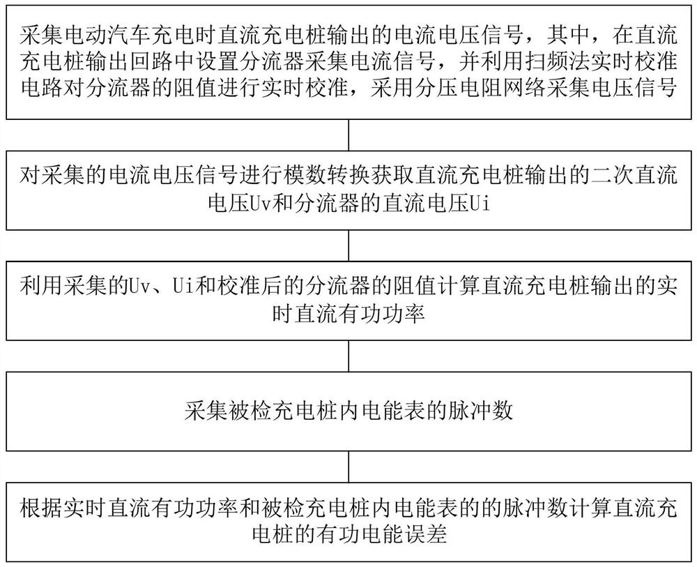
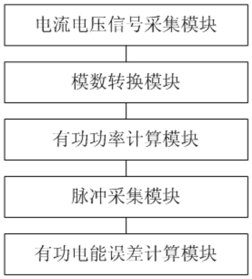
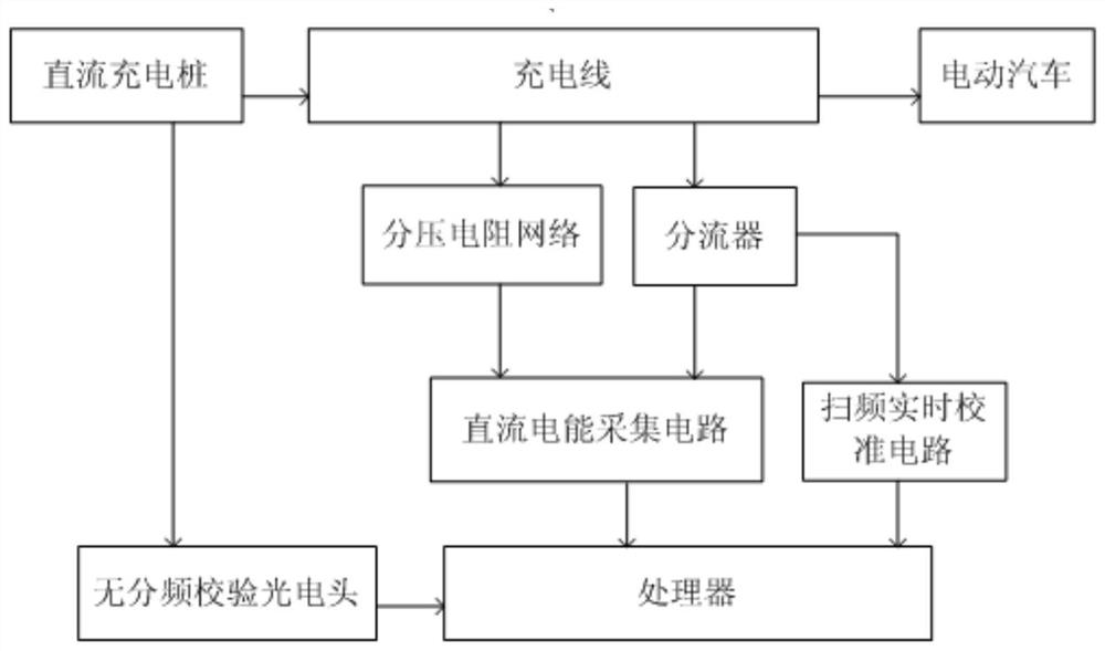
The invention discloses a direct current charging pile test method, device and equipment based on a sweep frequency calibration shunt. The test method comprises the following steps: collecting currentand voltage signals output by a direct current charging pile when an electric vehicle is charged, arranging a shunt in an output loop of the direct current charging pile to collect the current signal, calibrating the resistance value of the shunt in real time by using a sweep frequency method real-time calibration circuit, and collecting the voltage signal by using a divider resistance network; carrying out analog-to-digital conversion on the collected current and voltage signals to obtain secondary direct-current voltage Uv output by the direct-current charging pile and direct-current voltage Ui of the shunt; calculating real-time direct current active power output by the direct current charging pile by utilizing the acquired Uv and Ui and the calibrated resistance value of the shunt; collecting the pulse number of an electric energy meter in the detected charging pile; and calculating an active electric energy error of the DC charging pile according to the real-time DC active powerand the pulse number of the electric energy meter in the detected charging pile. The active electric energy error of the charging pile can be monitored, and fairness and justice of metering and billing of the charging pile of a charging pile operation company are ensured.

Description

technical field [0001] The invention relates to a DC charging pile testing method, device and equipment for calibrating the resistance value of a shunt based on a frequency sweep method, and belongs to the technical field of electric vehicle charging. Background technique [0002] Electric vehicle charging piles, like fuel dispensers, are measuring instruments used for trade settlement, and the accuracy of their measurement (billing) directly affects the economic interests of both parties to the trade. It is of great significance to carry out the legal management of measurement of electric vehicle charging piles, strengthen the measurement and supervision of charging piles, ensure the accuracy and reliability of the electric energy value of charging piles, and maintain the fairness and justice of electric energy trade settlement. [0003] As of May 2020, the cumulative number of charging infrastructure in the country is about 1.29 million units. Among them, the member units ...

Claims


Application Information

Patent Timeline
Patent Type & Authority Applications(China)
IPC IPC(8): G01R31/00G01R35/04G01R19/25
CPCG01R31/00G01R35/04G01R19/25Y02T10/70Y02T10/7072Y02T90/12
Inventor 陈祉如黄建钟董贤光代燕杰张志荆臻杜艳李琮琮王平欣王清朱红霞杨杰王婷婷徐子骞
Owner 国网山东省电力公司营销服务中心(计量中心)
Learn More