
Ion implanter and ion implantation method

An ion implantation device and ion beam technology, which are used in measurement devices, neutron radiation measurement, radiation/particle processing, etc., can solve problems such as cost increase, and achieve the effect of neutron dose rate suppression

Pending Publication Date: 2020-09-29
SUMITOMO HEAVY IND ION TECH
View PDF2 Cites 0 Cited by
  • Summary
  • Abstract
  • Description
  • Claims
  • Application Information

AI Technical Summary

Problems solved by technology

However, if a plurality of neutron beam detectors are arranged along a long beamline in order to measure neutron rays with high accuracy over the entire beamline, the cost will increase significantly

Method used


Image

  • Ion implanter and ion implantation method
  • Ion implanter and ion implantation method
  • Ion implanter and ion implantation method

Examples


Embodiment approach

[0210] Another embodiment of this embodiment is as follows.

[0211] (item 2-1)

[0212] An ion implantation device, characterized in that it has:

[0213] a plurality of devices arranged along a beamline for transmitting the ion beam;

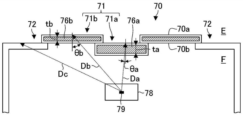
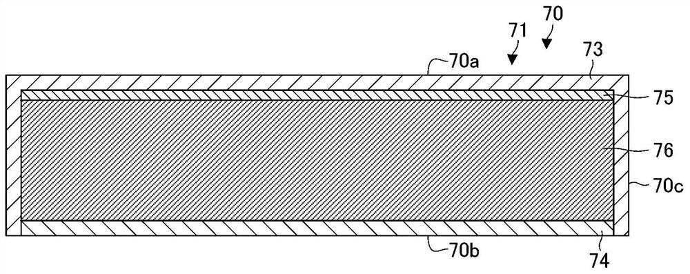
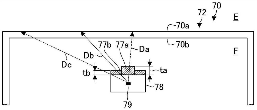
[0214] a plurality of neutron ray detectors arranged at a plurality of positions near the beamline, and measuring neutron rays that may be generated at a plurality of positions of the beamline due to collision of high-energy ion beams; and

[0215] The control device monitors at least one of the plurality of devices based on a measurement value of at least one neutron beam detector among the plurality of neutron beam detectors.

[0216] (Item 2-2)

[0217] The ion implantation apparatus according to item 2-1, characterized in that,

[0218] The control device estimates the position of a neutron beam generation source at least one of the beamlines based on the measured values ​​of the plurality of neutron beam detectors.

[0219] (items 2...


PUM


Abstract

The invention aims to appropriately monitor the generation status of neutron rays at low cost. An ion implanter (100) includes: a plurality of devices which are disposed along a beamline (BL) along which an ion beam is transported; a plurality of neutron ray measuring instruments (51,52,53,54) which are disposed at a plurality of positions in the vicinity of the beamline and measure neutron rays which are generated at a plurality of locations of the beamline due to collision of a high-energy ion beam; and a control device which monitors at least one of the plurality of devices, based on a measurement value in at least one of the plurality of neutron ray measuring instruments (51-54).

Description

technical field [0001] This application claims priority based on Japanese Patent Application No. 2019-051015 filed on March 19, 2019. The entire contents of this Japanese application are incorporated herein by reference. [0002] The invention relates to an ion implantation device and an ion implantation method. Background technique [0003] In the semiconductor manufacturing process, a process of implanting ions into a semiconductor wafer is routinely performed for the purpose of changing the conductivity, the purpose of changing the crystal structure of the semiconductor wafer, and the like. The equipment used in this process is generally called an ion implantation equipment. The ion implantation energy is determined according to the desired implantation depth of the ions implanted near the surface of the wafer. A low-energy ion beam is used for implantation into a shallow region, and a high-energy ion beam is used for implantation into a deep region. [0004] In recen...

Claims


Application Information

Patent Timeline
IPC IPC(8): H01J37/244H01J37/141H01J37/147H01J37/317
CPCH01J37/3171H01J37/141H01J37/1475H01J37/244H01J37/165H01J37/304H01J2237/184G21K1/10H01J37/045H01J37/147H01J2237/0473G01T3/00H01J2237/2448H01J37/1472
Inventor 松下浩
Owner SUMITOMO HEAVY IND ION TECH
Learn More