
Patch antenna and antenna array

A patch antenna and guide piece technology, which is applied to antenna arrays, individually powered antenna arrays, antennas, etc., can solve problems such as poor array S parameters, low antenna production and debugging efficiency, and antenna isolation deterioration.

Pending Publication Date: 2020-09-29
MOBILE ANTENNA TECH SHENZHEN +5
View PDF0 Cites 2 Cited by
  • Summary
  • Abstract
  • Description
  • Claims
  • Application Information

AI Technical Summary

Problems solved by technology

After the existing patch antenna is formed into an antenna array, its impedance characteristics and polarization isolation are usually seriously deteriorated due to the problem of the surrounding environment (small unit spacing), which causes great difficulties in the design and use of the antenna array, mainly manifested in The standing wave matching is difficult, and the antenna isolation is seriously deteriorated, and the S parameters of the array are not good
At this time, it is necessary to add some metal parts to the antenna array to adjust the isolation, but for the frequency of 3.5GHz, the size and position of the adjustment parts are slightly deviated, and the difference is relatively large, resulting in low production and debugging efficiency of the antenna.
[0004] In summary, there are obviously inconveniences and defects in the actual use of the existing technology, so it is necessary to improve

Method used

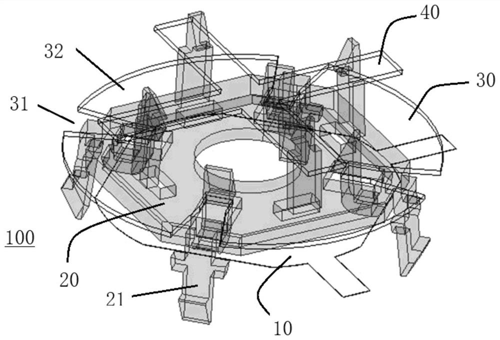
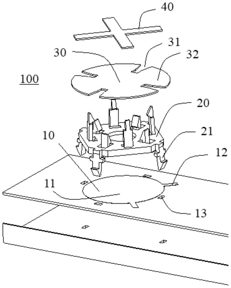
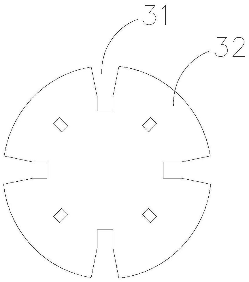

Image

  • Patch antenna and antenna array
  • Patch antenna and antenna array
  • Patch antenna and antenna array

Examples


Embodiment Construction

[0041] In order to make the object, technical solution and advantages of the present invention clearer, the present invention will be further described in detail below in conjunction with the accompanying drawings and embodiments. It should be understood that the specific embodiments described here are only used to explain the present invention, not to limit the present invention.

[0042] It should be noted that references in this specification to "one embodiment", "embodiment", "example embodiment" and the like mean that the described embodiment may include specific features, structures or characteristics, but not every Embodiments must include those specific features, structures or characteristics. Furthermore, such expressions are not referring to the same embodiment. Further, when specific features, structures or characteristics are described in conjunction with an embodiment, whether or not there is an explicit description, it has been indicated that it is within the kn...


PUM


Abstract

The invention provides a patch antenna. The patch antenna at least comprises a feed structure, a supporting piece and a near-field coupling piece, the supporting piece is fixed on the feed structure,and the near-field coupling piece is fixed on the supporting piece. The edge of the near-field coupling piece is provided with at least one pair of symmetrical slots. The invention further provides anantenna array with at least one patch antenna. Therefore, the antenna isolation can be obviously improved, the S parameter of the patch antenna in the array is improved, and the directional diagram index is not influenced.

Description

technical field [0001] The invention relates to the technical field of mobile antennas, in particular to a patch antenna and an antenna array. Background technique [0002] With the development of the global 5G communication system, operators have successively used base stations and antennas in the 3.5GHz frequency band. Due to its frequency coverage characteristics, the matching base station deployment of 3.5GHz is generally relatively small, and the base station + antenna method is adopted, corresponding to the The antenna thickness is also relatively low. Due to the restriction on the thickness of the antenna, the antenna unit often uses a low-profile unit, and the patch antenna is usually the first choice. [0003] Existing patch antennas usually have direct feeding, coupling feeding, etc., that is, direct feeding through probes and direct feeding through microstrip lines, called direct feeding; and the coupling method of using feeding sheets and radiation sheets Perfo...

Claims


Application Information

Patent Timeline
IPC IPC(8): H01Q1/12H01Q1/36H01Q1/50H01Q1/52H01Q21/00H01Q21/06
CPCH01Q1/12H01Q1/36H01Q1/523H01Q1/50H01Q21/0006H01Q21/065
Inventor 刘朋邬烈锋王羽林刘维卓徐可
Owner MOBILE ANTENNA TECH SHENZHEN
Learn More