
Heat shrink tube heating device

A technology of heating device and heat-shrinkable tube, which is applied in the assembly/disassembly of contacts, electrical components, circuits, etc., which can solve the problems of low efficiency of manual operation, poor heating quality of heating tubes, heating damage of wiring harness, etc., and reduce labor costs. Labor intensity, improved heating quality, and uniform heating effect

Active Publication Date: 2020-09-29
上海发之源电气有限公司
View PDF4 Cites 2 Cited by
  • Summary
  • Abstract
  • Description
  • Claims
  • Application Information

AI Technical Summary

Problems solved by technology

[0004] The above existing technical solutions have the following defects: when the heating tube needs to be heated, the wire harness and the heating tube are manually placed on the conveyor belt, and then the whole is heated by the heating tube, and when heating, the heating tube faces the side of the heating tube. One side is mainly heated, and the heating is uneven. The above problems lead to poor heating quality of the heating tube, damage to the heating of the wire harness, and low efficiency of manual operation.

Method used


Image

  • Heat shrink tube heating device
  • Heat shrink tube heating device
  • Heat shrink tube heating device

Examples


Embodiment Construction

[0034] The present invention will be described in further detail below in conjunction with the accompanying drawings.

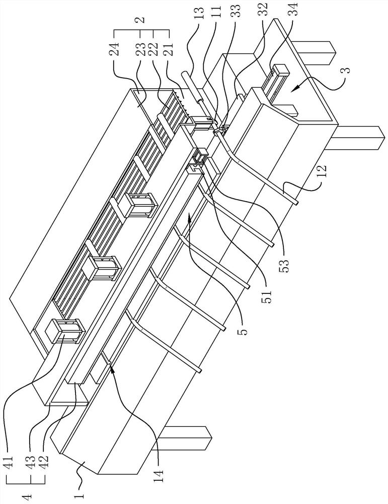
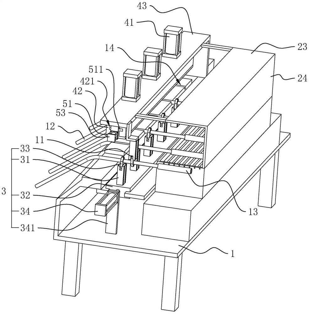
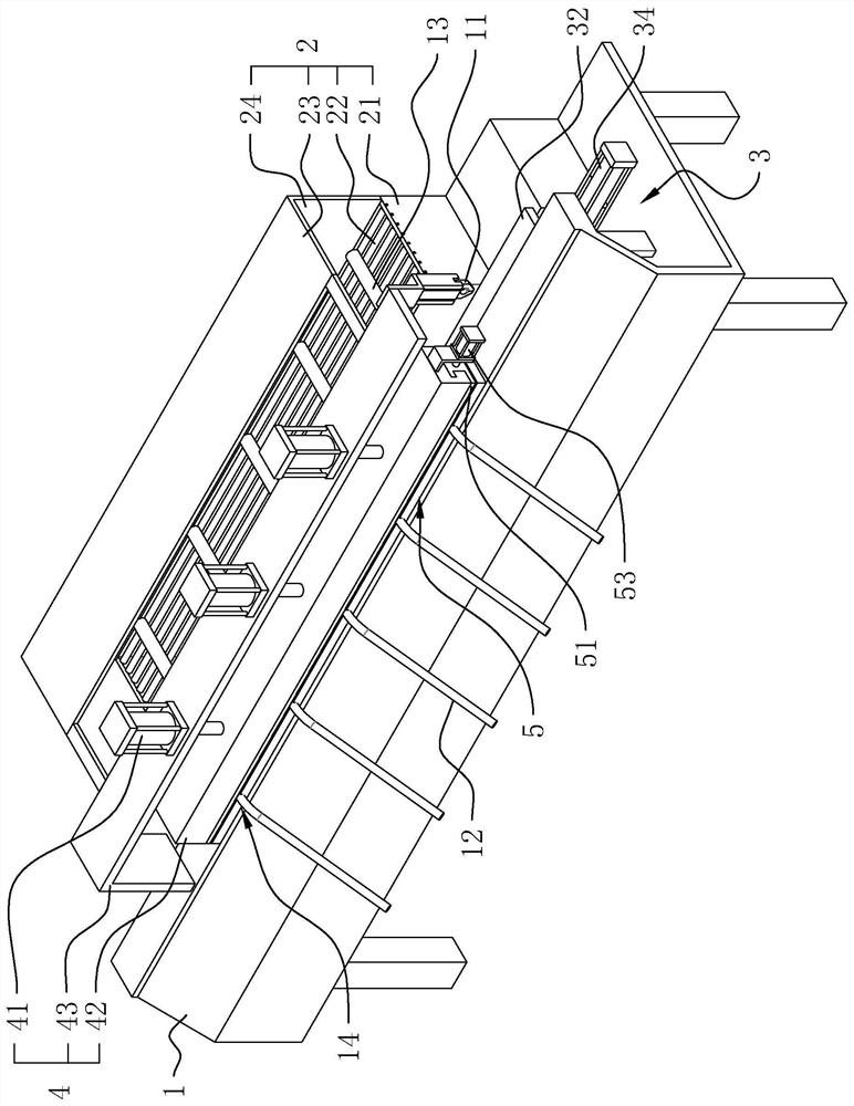
[0035] refer to figure 1 and figure 2 , is a heat-shrinkable tube heating device disclosed in the present invention, comprising a support frame 1, and the two ends of the support frame 1 are respectively set as a feed end and a discharge end. One side of the feeding end is provided with a vertically downward feeding mechanical claw 11 , the wire harness 12 is clamped under the feeding mechanical claw 11 , and one end of the wire harness 12 is wrapped with a heat shrinkable tube 13 . The discharge end is provided with the same discharge mechanical claw (not shown in the figure) as the feed mechanical claw 11, and the discharge mechanical claw can move toward the next process.

[0036]One side of the support frame 1 between the feed end and the discharge end is provided with a heating assembly 2 for heating the heat shrinkable tube 13 wrapping the wire harne...


PUM


Abstract

The invention relates to a heat shrink tube heating device, belongs to the technical field of wire harness machining equipment and solves technical problems that a heating pipe on a wire harness is low in heating efficiency and poor in heating quality. The device comprises a support frame, wherein one side of the support frame is provided with a heating assembly used for heating a heat shrink tubewrapping a wire harness, a moving assembly used for accurately moving the heat shrink tube is arranged above the other side of the support frame, the moving assembly comprises a plurality of pneumatic mechanical claws used for clamping the wire harness, a positioning assembly used for pressing and positioning the heat shrink tube wrapping the wire harness is arranged above the supporting frame, and a rotating assembly used for rotating the wire harness is arranged below the positioning assembly. The device has advantages of rapidly and uniformly heating the heat shrink tube and improving theheating quality and working efficiency of the heat shrink tube.

Description

technical field [0001] The invention relates to the technical field of wire harness processing equipment, in particular to a heat shrinkable tube heating device. Background technique [0002] A heat-shrinkable tube needs to be provided at the connection point between the connector and the wire harness, and the heat-shrinkable tube can be used to achieve the effect of insulation, sealing and waterproof at the connection point between the connector and the wire harness. When producing heat-shrinkable tubing, it needs to be heated to a highly elastic state, a load is applied to make it expand, and it is cooled rapidly while maintaining the expansion, so that it enters a glass state, and this state is fixed. When heated during use, the heat-shrinkable tube will return to a highly elastic state, but when the load is gone, it will retract. Because the heat-shrinkable tube has the functions of high-temperature shrinkage, softness, flame retardancy, insulation and corrosion resistan...

Claims


Application Information

Patent Timeline
IPC IPC(8): H01R43/00H01R43/20H01R4/72
CPCH01R4/72H01R43/005H01R43/20
Inventor 徐振思陆勇李林平
Owner 上海发之源电气有限公司
Learn More