Method and system for judging activated carbon heating effect and pre-judging working state of analysis tower

A technology of working status and heating effect, which is applied in the field of activated carbon to treat flue gas, and can solve the problems of inaccurate judgment of the heating effect of activated carbon and blockage of activated carbon

Active Publication Date: 2021-02-26
ZHONGYE-CHANGTIAN INT ENG CO LTD
View PDF2 Cites 0 Cited by
  • Summary
  • Abstract
  • Description
  • Claims
  • Application Information

AI Technical Summary

Problems solved by technology

[0010] Aiming at the problem in the prior art that the activated carbon may be blocked in the heating section of the desorption tower and the heating effect of the activated carbon cannot be accurately judged, the present invention proposes a method and system for judging the heating effect of the activated carbon and predicting the working state of the desorption tower

Method used


Image

  • Method and system for judging activated carbon heating effect and pre-judging working state of analysis tower
  • Method and system for judging activated carbon heating effect and pre-judging working state of analysis tower
  • Method and system for judging activated carbon heating effect and pre-judging working state of analysis tower

Examples


Embodiment 1

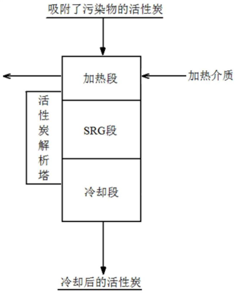
[0123] Such as Figure 7 As shown, a system for judging the heating effect of activated carbon and predicting the working state of the desorption tower includes an activated carbon desorption tower 1 . According to the direction of the activated carbon, the activated carbon desorption tower 1 is provided with a heating section 101, an SRG section 102, and a cooling section 103 sequentially from top to bottom. The sidewall of the SRG section 102 is provided with an SRG gas outlet 104 . The top of the activated carbon analysis tower 1 is provided with an activated carbon feed port, and the bottom of the activated carbon analysis tower 1 is provided with an activated carbon discharge outlet. A heating medium inlet and a heating medium outlet are provided on the side wall of the heating section 101 . The activated carbon inlet of the heating section 101 is provided with a first flow detection device 401 and a first temperature detection device 501 . A second flow detection devi...

Embodiment 2

[0125] Repeat embodiment 1, only the top of the activated carbon feed inlet of activated carbon analysis tower 1 is provided with feed bin, and feed bin bottom is provided with weighing device 3.

Embodiment 3

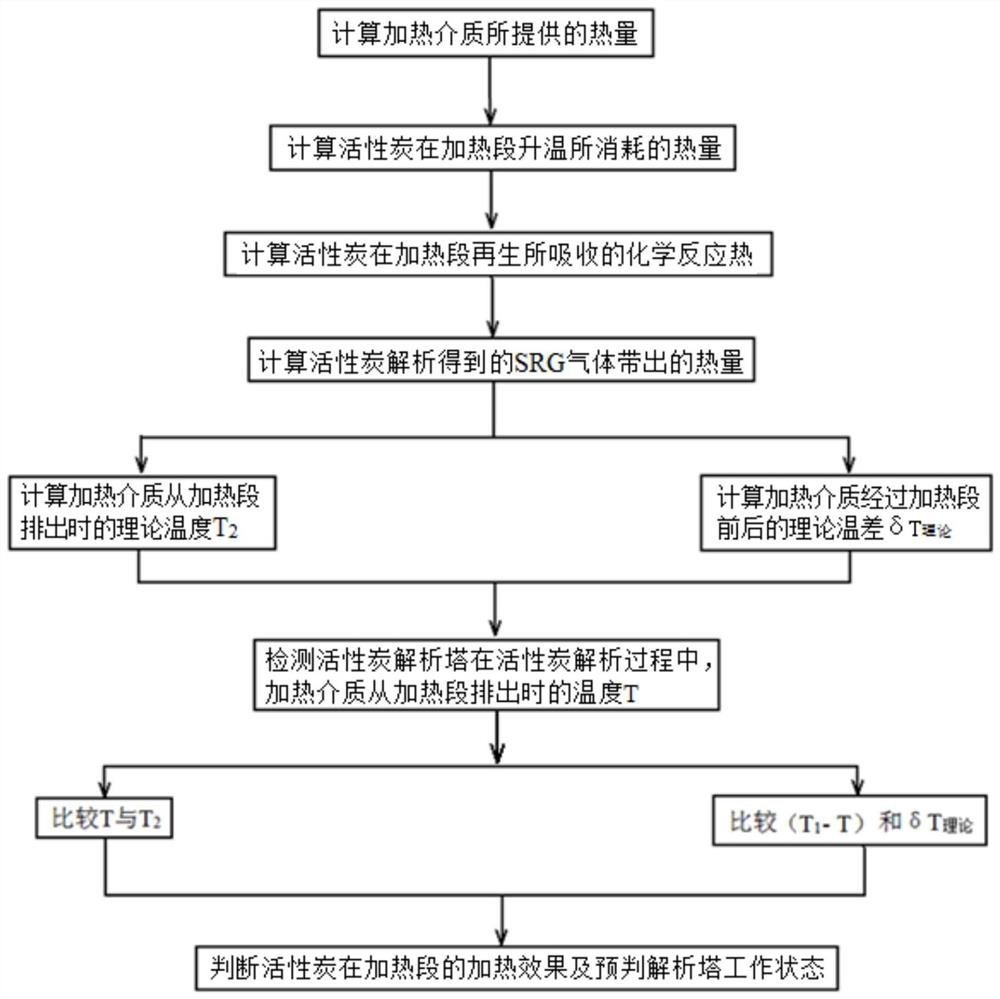
[0127] Such as Figure 8 As shown, embodiment 2 is repeated, except that the system also includes a control system 7 . The control system 7 and the first flow detection device 401, the first temperature detection device 501, the second flow detection device 402, the second temperature detection device 502, the third flow detection device 403, the sulfur dioxide concentration detection device 6, and the fourth flow detection device 404, the fourth temperature detection device 504, the fifth temperature detection device 505 are connected, and calculate the theoretical temperature difference before and after the heating medium passes through the heating section 101 according to formula (I) or formula (M) in real time, or according to formula (J) or formula ( N) calculate the theoretical temperature when the heating medium is discharged from the heating medium outlet of the heating section 101;

[0128] δT 理论 =T 1 -T 2 =(c 2 q 2 (t 2 -t 1 )+q 3 Cso 2 / 64*δh+c 3 q 4 ...


PUM


Abstract

The invention provides a method and a system for judging heating effect of activated carbon and pre-judging working state of an analysis tower, which judge the heating effect of the activated carbon in a heating section and pre-judge the working state of the analysis tower by monitoring the temperature of a heating medium entering the heating section and the temperature of the heating medium discharged out of the heating section according to the heat balance mode of the heating section of the analysis tower. According to the method and the system provided by the invention, the heating effect of the activated carbon in the heating section can be quickly and accurately judged and the working state of the desorption tower can be pre-judged from the perspective of heat balance.

Description

technical field [0001] The invention relates to a method and a system for treating activated carbon in an analytic tower, in particular to a method and a system for judging the heating effect of activated carbon and predicting the working state of an analytic tower, belonging to the technical field of flue gas treatment by activated carbon. Background technique [0002] Activated carbon flue gas purification technology has the advantages of synergistic and efficient purification of multiple pollutants, and is suitable for complex sintering flue gas components (SO 2 , NO x , dust, O 2 , water vapor, heavy metals), and large temperature fluctuations (110-180°C), it has been successfully applied to the sintering flue gas purification system. [0003] The activated carbon flue gas purification system is equipped with multiple subsystems such as an adsorption system, an analysis system, and an acid system. Thermal desorption activation (to release pollutants) → cooling → adsor...

Claims


Application Information

Patent Timeline
IPC IPC(8): B01J20/34B01J20/20B01D53/04
CPCB01J20/3416B01J20/3458B01J20/3483B01J20/20B01D53/04B01D2253/102B01D2259/40088Y02A50/20
Inventor 李俊杰魏进超李勇何凯琳
Owner ZHONGYE-CHANGTIAN INT ENG CO LTD
Why Eureka
Try Eureka