Supercharge Your Innovation With Domain-Expert AI Agents!

Method for detecting photoelectric property of laser Bar chip

A technology of optoelectronic performance and detection method, applied in lasers, laser parts, semiconductor lasers, etc., can solve the problems of low efficiency of positioning mechanism, difficult operation, incontinence, etc., to achieve convenient and accurate power supply, simple fine-tuning positioning, and high detection efficiency Effect

Active Publication Date: 2020-09-29
哈工大机器人南昌智能制造研究院
View PDF16 Cites 0 Cited by
  • Summary
  • Abstract
  • Description
  • Claims
  • Application Information

AI Technical Summary

Problems solved by technology

[0003] 1. The loading of the bars is not smart enough and cannot be continuous. The general operation is to manually use the pneumatic suction nozzle or other tools to place the bars on the detection platform for inspection. It cannot guarantee that the bars have been aligned, and manual operation also has May cause damage to the chip on the bar
[0004] 2. The current detection method manually sends the bar to the detection platform. Because the placement position is incorrect, it is generally necessary to adjust the position of the bar, but the operation of adjusting the position is inconvenient and difficult to operate. The positioning adjustment method is somewhat The bar is moved through the experience of the workers and human eyes, and some are positioned by adding an additional positioning mechanism, but the efficiency of the added positioning mechanism is low. At the same time, because the bar is relatively thin, the installation of the positioning mechanism is very difficult to debug
And the positioning mechanism also takes up a certain amount of equipment space
[0005] 3. Since there are multiple chips on the bar, and the position of the bar is difficult to locate, the position of each chip is inaccurate. When performing a performance test on each chip, it is necessary to conduct conduction on each chip to make it light, and the current detection device is unable to conduct electricity to the chips with inaccurate positions one by one, so it is impossible to efficiently inspect all the chips on the bar, especially for the detection of its photoelectric performance. Its luminous intensity and divergence angle detection efficiency is low

Method used


Image

  • Method for detecting photoelectric property of laser Bar chip
  • Method for detecting photoelectric property of laser Bar chip
  • Method for detecting photoelectric property of laser Bar chip

Examples


Embodiment Construction

[0064] The present invention will be described in further detail below through specific examples.

[0065] A method for detecting photoelectric properties of a laser bar chip, comprising the following steps:

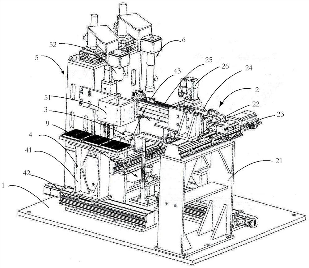
[0066] S1, place the Bar box 43 with many Bar bars on the Bar bar detection station of the placement seat 41; wherein, the Bar box 43 is provided with several Bar bar placement grooves 432, each Bar bar All are placed in the corresponding Bar bar placement groove 432; Place at least two Bar barrel boxes 43 on the placement seat 41, after the Bar bars in one of the Bar box boxes 43 have all been detected, the placement seat 41 moves a station to make The next Bar box 43 moves to the Bar bar detection station for the next round of detection.

[0067] S2. Use the Bar detection camera 52 to take photos of the Bar box 43 on the Bar detection station to confirm the placement position of the Bar in the Bar box 43; wherein, the parallel ring light can be used to supplement ligh...


PUM


Abstract

The invention discloses a method for detecting the photoelectric property of a laser Bar strip chip. The method comprises the following steps: S1, placing a Bar strip box on a placement seat; S2, determining the placing positions of the Bar strips; S3, transferring the Bar strips to a detection platform; S4, finely adjusting and positioning the Bar strips; S5, enabling the chip to be located at achip detection station; S6, detecting the appearance and the position of the chip; S7, supplying power to enable the chip to emit light; S8, carrying out luminous intensity detection on the chip; S9,moving to avoid the detection space; S10, respectively detecting a horizontal divergence angle and a vertical divergence angle of the chip; S11, separating and stopping power supply; S12, completing the detection of all the chips on the Bar strips; S13, transferring the detected chip into a Bar strip box; and S14, repeatedly detecting until all the Bar chips in the Bar strip box are detected. According to the detection method, all the chips on all the Bar strips in the Bar strip box can be continuously and completely detected, and the detection efficiency is higher.

Description

technical field [0001] The invention relates to a photoelectric property detection method of a laser bar chip, belonging to the field of laser semiconductor detection. Background technique [0002] The detection of laser bar chips is an important process in the production process of laser chips. However, the current detection method has several disadvantages: [0003] 1. The loading of the bars is not smart enough and cannot be continuous. The general operation is to manually use the pneumatic suction nozzle or other tools to place the bars on the detection platform for inspection. It cannot guarantee that the bars have been aligned, and manual operation also has It may cause damage to the chip on the bar. [0004] 2. The current detection method manually sends the bar to the detection platform. Because the placement position is incorrect, it is generally necessary to adjust the position of the bar, but the operation of adjusting the position is inconvenient and difficult ...

Claims


Application Information

Patent Timeline
Patent Type & Authority Applications(China)
IPC IPC(8): H01S5/00B65G47/91
CPCB65G47/912H01S5/0014
Inventor 赵亮涂洪森王志刚邹宇
Owner 哈工大机器人南昌智能制造研究院
Features
  • R&D
  • Intellectual Property
  • Life Sciences
  • Materials
  • Tech Scout
  • Unparalleled Data Quality
  • Higher Quality Content
  • 60% Fewer Hallucinations
Learn More