Synchronous phase modifier configuration method of extra-high voltage direct current weak receiving end power grid

A technology of UHV DC and configuration method, which is applied in the direction of circuit devices, AC network circuits, electrical components, etc., can solve the problems of synchronous condenser without optimization, difficulty in fully exerting the voltage support function of the condenser's fast reactive power adjustment ability, etc., to achieve Good promotion and application value, simple and effective configuration method, and the effect of improving the load carrying capacity

Active Publication Date: 2020-09-29
STATE GRID HUNAN ELECTRIC POWER +2
View PDF2 Cites 2 Cited by
  • Summary
  • Abstract
  • Description
  • Claims
  • Application Information

AI Technical Summary

Problems solved by technology

[0004] Considering that the main goal of synchronous condenser configuration in the prior art is to improve system transient voltage stability and suppress transient overvoltage, the configuration of synchronous condenser has not been optimized from the overall demand for voltage stability of UHV DC weak receiving end grid, thus It is difficult to give full play to the fast reactive power adjustment capability of the condenser to support the voltage of the receiving end grid

Method used


Image

  • Synchronous phase modifier configuration method of extra-high voltage direct current weak receiving end power grid
  • Synchronous phase modifier configuration method of extra-high voltage direct current weak receiving end power grid
  • Synchronous phase modifier configuration method of extra-high voltage direct current weak receiving end power grid

Examples


Embodiment Construction

[0043] The present invention will be clearly and completely described below in conjunction with the accompanying drawings and embodiments, and the technical problems and beneficial effects solved by the technical solutions of the present invention are also described. It should be pointed out that the described embodiments are only intended to facilitate the implementation of the present invention understood without any limitation.

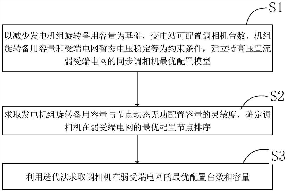
[0044] Based on the technical problems that are not easy to find, the present invention specifically provides a method for configuring a synchronous condenser in an UHV DC weak receiving end power grid. The optimal configuration model of the power grid uses the perturbation method to obtain the sensitivity of the rotating reserve capacity of the generator set and the dynamic reactive power configuration capacity of the node and the iterative method to obtain the optimal configuration point and number of condensers in the weak receiving end power gri...


PUM


Abstract

The invention discloses a synchronous phase modifier configuration method of an extra-high voltage direct current weak receiving end power grid. The method comprises the following steps of establishing an optimal configuration model of a synchronous phase modifier, and considering constraint conditions such as the number of configurable phase modifiers of a transformer substation, the spinning reserve capacity of a generator set and the transient voltage stability of a receiving-end power grid on the basis of reducing the spinning reserve capacity of the generator set reserved for keeping thetransient voltage stability of the weak receiving-end power grid; determining the optimal configuration node sequence of the phase modifier in a weak receiving end power grid according to the sensitivity relationship between the generator set spinning reserve capacity and the node dynamic reactive configuration capacity; and solving the optimal configuration number and capacity of the phase modifier in the weak receiving end power grid by using the optimal configuration node sorting and iteration method. The method is advantaged in that the transient voltage supporting effect of the phase modifier on the weak receiving end power grid can be effectively improved, the spinning reserve capacity of the generator set is released, the on-load capacity of the generator set in the load peak periodis improved, and a good engineering application value is achieved.

Description

technical field [0001] The invention relates to the technical field of dynamic reactive power configuration, in particular to a synchronous condenser configuration method for an UHV DC weak receiving end power grid. Background technique [0002] With the development of UHVDC transmission system and the increase of transmission power, the voltage stability problem of the DC receiving end power grid has become increasingly prominent. It is mainly reflected in the fact that UHV DC is generally fed into load-intensive areas, and the reactive power required during the rapid recovery process of its commutation failure increases significantly, resulting in insufficient dynamic reactive power support of the power grid in load-intensive areas, and a high risk of voltage instability in the receiving end power grid. At present, configuring dynamic reactive power compensation equipment in the UHV DC weak receiving end grid is an effective measure to improve the transient voltage stabili...

Claims


Application Information

Patent Timeline
Patent Type & Authority Applications(China)
IPC IPC(8): H02J3/18
CPCH02J3/1885H02J2203/20Y02E40/30
Inventor 崔挺胡臻陈道君王玎邹妍晖沈阳武呙虎向萌柳永妍
Owner STATE GRID HUNAN ELECTRIC POWER
Why Eureka
Try Eureka