Mechanical PEEP valve and emergency ventilator with PEEP valve

A mechanical and valve body technology, applied in the field of medical devices, can solve problems such as increasing pain, and achieve the effects of increasing oxygenation time, improving oxygenation state, and prolonging exhalation time

Pending Publication Date: 2020-10-02
THE FIRST AFFILIATED HOSPITAL OF HENAN UNIV OF SCI & TECH
View PDF4 Cites 0 Cited by
  • Summary
  • Abstract
  • Description
  • Claims
  • Application Information

AI Technical Summary

Problems solved by technology

But there are still some deficiencies, mainly in: although the patient can maintain a certain airway pressure at the end of exhalation, the patient will encounter greater

Method used


Image

  • Mechanical PEEP valve and emergency ventilator with PEEP valve
  • Mechanical PEEP valve and emergency ventilator with PEEP valve
  • Mechanical PEEP valve and emergency ventilator with PEEP valve

Examples


Embodiment 1

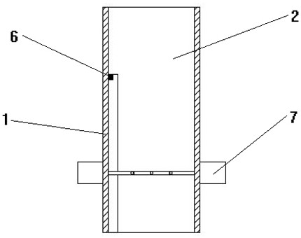
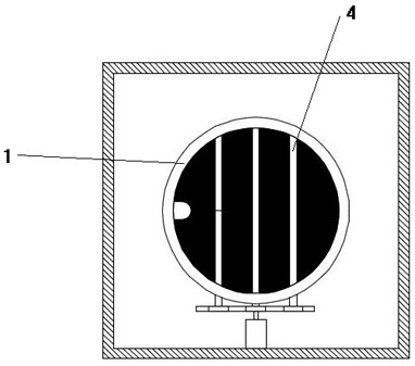
[0038] As shown in the figure: a mechanical PEEP valve mainly includes a valve body 1 , a movable shutter mechanism and a control mechanism, and the valve body 1 has an exhalation channel 2 . The movable flap mechanism is used to change the gas flow rate of the exhalation channel 2 of the valve body 1 . The control mechanism is used to control the movable shutter mechanism to perform intermittent actions.

[0039] The movable flap mechanism has three flaps 3, and the outer edge of the flaps 3 is provided with a flexible layer. In the expiratory channel 2 of the valve body 1, the flap 3 is driven by the control mechanism to switch between the initial state and the flipped state. In this state, the axial directions of the blocking pieces 3 and the exhalation channel 2 are perpendicular to each other, and when the four blocking pieces 3 are turned over, the exhalation channel 2 can be completely blocked.

[0040] The movable shutter mechanism also includes an outer collar 7, whic...

Embodiment 2

[0048] As shown in the figure: a mechanical PEEP valve mainly includes a valve body 1 , a movable shutter mechanism and a control mechanism, and the valve body 1 has an exhalation channel 2 . The movable flap mechanism is used to change the gas flow rate of the exhalation channel 2 of the valve body 1 . The control mechanism is used to control the movable shutter mechanism to perform intermittent actions.

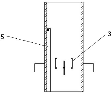
[0049] The movable flap mechanism has three flaps 3, the outer edge of the flaps 3 is attached with a flexible layer 12, and the two ends of the flaps 3 are arc-shaped compatible with the inner wall of the exhalation channel 2, and the flaps 3 are set by the rotating shaft 4 In the expiratory channel 2 of the valve body 1, the flap 3 is driven by the control mechanism to switch between the initial state and the overturned state. In the initial state, the axial directions of the flap 3 and the exhalation channel 2 are parallel to each other. In the overturned state, the axi...

Embodiment 3

[0055] As shown in the figure: a mechanical PEEP valve mainly includes a valve body 1 , a movable shutter mechanism and a control mechanism, and the valve body 1 has an exhalation channel 2 . The movable flap mechanism is used to change the gas flow rate of the exhalation channel 2 of the valve body 1 . The control mechanism is used to control the movable shutter mechanism to perform intermittent actions.

[0056] The movable flap mechanism has three flaps 3, the outer edge of the flaps 3 is attached with a flexible layer 12, and the two ends of the flaps 3 are arc-shaped compatible with the inner wall of the exhalation channel 2, and the flaps 3 are set by the rotating shaft 4 In the expiratory channel 2 of the valve body 1, the flap 3 is driven by the control mechanism to switch between the initial state and the overturned state. In the initial state, the axial directions of the flap 3 and the exhalation channel 2 are parallel to each other. In the overturned state, the axi...


PUM


Abstract

The invention relates to a mechanical PEEP valve and an emergency ventilator with the PEEP valve. The mechanical PEEP valve comprises a valve body, a movable separation blade mechanism and a control mechanism. The movable separation blade mechanism comprises at least two separation blades, the separation blades are arranged in an expiration channel of the valve body through rotating shafts, the separation blades are driven by the control mechanism to be switched between an initial state and an overturning state, the separation blades and the axial direction of the expiration channel are parallel to each other in the initial state, and the separation blades and the axial directions of the expiration channel are perpendicular to each other in the overturning state; the control mechanism comprises a driving motor, a signal induction assembly and an adjustable transmission assembly. The driving motor can drive all or part of the rotating shafts to rotate through the adjustable transmissionassembly. The mechanical PEEP valve can make a patient have a smooth expiration without obstruction in the initial stage of expiration, and can reduce the flow of the expiration channel in the laterstage of expiration, so that resistance is applied to the expiration of the patient, expiration time is prolonged, oxygenation time is prolonged, and an oxygenation state is improved.

Description

technical field [0001] The invention relates to the technical field of medical devices, in particular to a mechanical PEEP valve and an emergency ventilator with the PEEP valve. Background technique [0002] In the rescue of patients with respiratory arrest in hospitals, ventilators are generally used to help patients breathe and ventilate. However, after the patient exhales air, the pressure in his lungs drops rapidly to one atmospheric pressure, which rapidly reduces the functional residual capacity in the patient's lungs, making it difficult for the residual gas in the patient's lungs to keep the alveoli at a certain volume, and at the same time due to The patient's own lung function is not perfect, which is likely to lead to the shrinkage of the patient's alveoli; and the sharp drop in the patient's lung pressure reduces the compliance of the lung, and the ventilation and oxygenation status are poor. Therefore, there is a need to provide a device that can improve the ab...

Claims


Application Information

Patent Timeline
IPC IPC(8): A61M16/20A61M16/00H02K7/06H02K7/116
CPCA61M16/202A61M16/00A61M16/0003H02K7/116H02K7/06A61M2016/003
Inventor 杨莉王玉华肖飞陆兆丰张淑梅胡莹莹代国方
Owner THE FIRST AFFILIATED HOSPITAL OF HENAN UNIV OF SCI & TECH
Why Eureka
Try Eureka