
Hot forging machining process of forklift separation sleeve

A technology of separation sleeve and processing technology, which is applied in the field of forklift parts processing, and can solve the problems that the continuous forging of the separation sleeve cannot be realized.

Active Publication Date: 2020-10-02
YUEXI SHENGHONG IND & TRADE
View PDF8 Cites 0 Cited by
  • Summary
  • Abstract
  • Description
  • Claims
  • Application Information

AI Technical Summary

Problems solved by technology

[0003] The purpose of the present invention is to provide a hot forging process for the separation sleeve of a forklift. In the present invention, a feeding mechanism is provided on one side of the base, a plurality of hanging plates are hinged on the transmission belt, and a hanging rod is installed on the hanging plate for Place the forklift separation sleeve forgings, drive the transmission wheel to rotate through the drive motor, and drive the transmission belt to rotate, to drive each hanging rod to move, thereby driving each forklift separation sleeve forging to move, so that the forklift separation sleeve forgings move to the supporting mechanism On the one hand, the invention can drive a plurality of forklift separation sleeve forgings to move rapidly at the same time, which ensures the continuous forging of the forklift separation sleeve, improves the work efficiency, and solves the problem that the traditional hot forging process of the forklift separation sleeve cannot be realized. Technical problems of continuous forging of split sleeves;

Method used


Image

  • Hot forging machining process of forklift separation sleeve
  • Hot forging machining process of forklift separation sleeve
  • Hot forging machining process of forklift separation sleeve

Examples


Embodiment Construction

[0035] The technical solutions of the present invention will be clearly and completely described below in conjunction with the embodiments. Apparently, the described embodiments are only some of the embodiments of the present invention, not all of them. Based on the embodiments of the present invention, all other embodiments obtained by persons of ordinary skill in the art without creative efforts fall within the protection scope of the present invention.

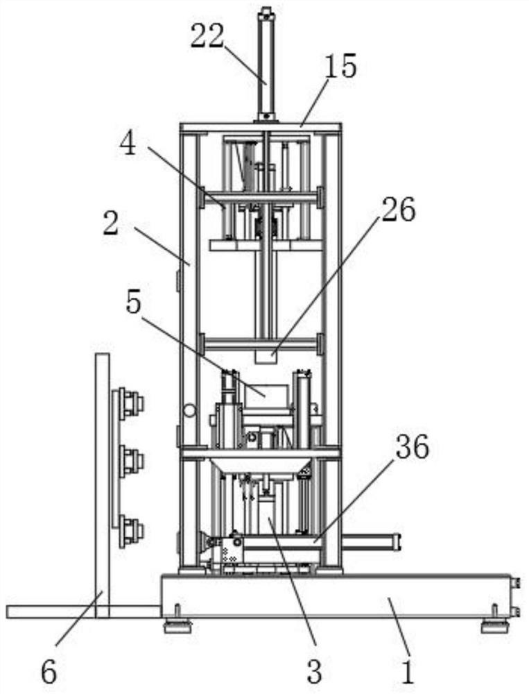
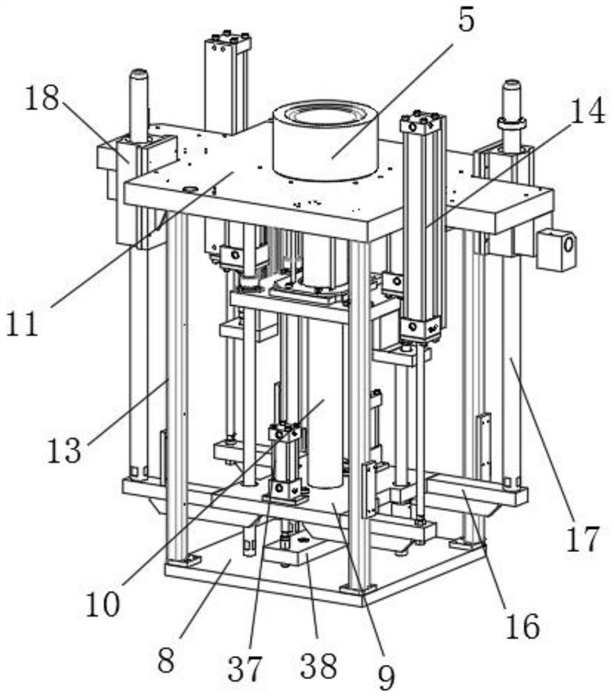
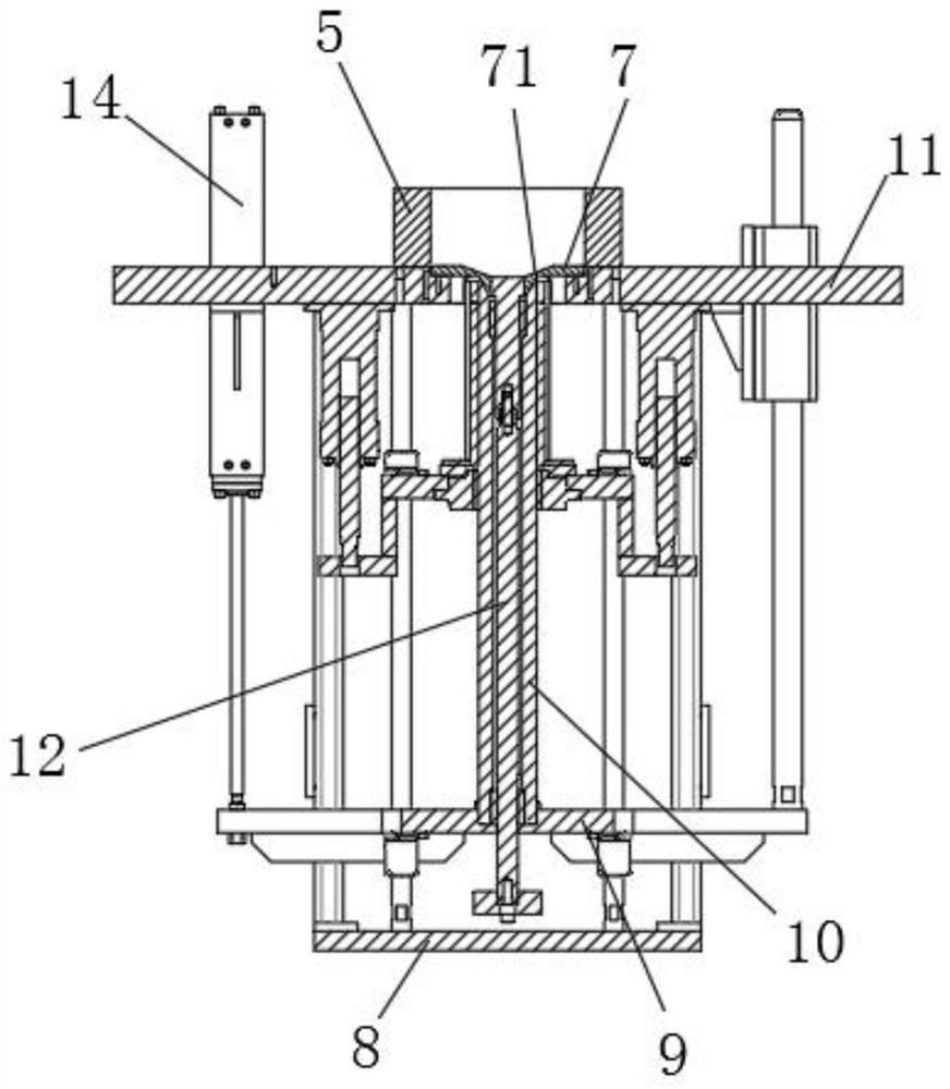
[0036] like Figure 1-7 As shown, a hot forging process of a forklift separation sleeve, the specific steps of this process are as follows:

[0037] Step 1. Hang the forklift separation sleeve forging on the hanging rod 32 of the forging device, start the driving motor 35, and the driving motor 35 drives the transmission wheel 29 to rotate, and drives the transmission belt 30 to rotate. When the transmission belt 30 rotates, it drives each hanging plate 31 moves, and drives the forklift separation sleeve forging to move to...


PUM


Abstract

The invention discloses a hot forging machining process of a forklift separation sleeve. The machining process comprises the steps that a forklift separation sleeve forge piece is transported, the forklift separation sleeve forge piece is transferred into a forging and pressing groove, the forklift separation sleeve forge piece is forged, and the forklift separation sleeve forge piece is taken out. A forging and pressing device comprises a base, two supporting side frames are fixedly mounted on the surface of the base through welding, a supporting top plate is fixedly mounted at the tops of the supporting side frames through bolts, a material supporting mechanism and an upper pressing mechanism are arranged between the two supporting side frames, and a feeding mechanism is arranged on oneside of the base. According to the hot forging machining process of the forklift separation sleeve, continuous forging of the forklift separation sleeve is guaranteed, the working efficiency is improved, automatic operation is adopted in the transferring process, workers are effectively prevented from being injured, the forklift separation sleeve forge piece can be rapidly forged and formed, the forklift separation sleeve is rapidly taken out, the production efficiency is improved, and the forging and pressing device is convenient to overhaul.

Description

technical field [0001] The invention relates to the technical field of forklift parts processing, in particular to a hot forging process of a forklift separation sleeve. Background technique [0002] The release sleeve outside the release bearing on the forklift is an important part that drives the release bearing to move. The traditional hot forging process of the forklift release sleeve cannot carry out batch transportation of the forklift release sleeve forgings, nor can it realize the continuous forging of the forklift release sleeve. , in the processing process, the forgings need to be manually transferred to the forklift separation sleeve forgings, and the staff are easily injured. Moreover, the traditional hot forging process of the forklift separation sleeve is slow for the forging of the forklift separation sleeve, and it is impossible to quickly take out the finished product. Production low efficiency. Contents of the invention [0003] The purpose of the presen...

Claims


Application Information

Patent Timeline
IPC IPC(8): B21K1/76B21K7/12B21K27/00B21J5/00B21J13/14B21J9/02
CPCB21K1/76B21K7/12B21K27/00B21J5/00B21J13/14B21J9/02
Inventor 刘振国
Owner YUEXI SHENGHONG IND & TRADE
Features
  • Generate Ideas
  • Intellectual Property
  • Life Sciences
  • Materials
  • Tech Scout
  • Unparalleled Data Quality
  • Higher Quality Content
  • 60% Fewer Hallucinations
Learn More