
Stainless steel pipe cutting machine capable of automatically feeding and assisting in pressing after cutting

A stainless steel tube, automatic feeding technology, applied in the direction of shearing device, shearing device, metal processing machinery parts, etc., can solve the problems of unsafe, time-consuming and laborious, unstable, etc. The effect of improving the cutting quality

Active Publication Date: 2020-10-02
永康市明科自动化设备有限公司
View PDF9 Cites 0 Cited by
  • Summary
  • Abstract
  • Description
  • Claims
  • Application Information

AI Technical Summary

Problems solved by technology

[0002] There are many applications of stainless steel pipes in daily life, such as anti-theft windows, guardrails, etc. The most common way of processing is manual circular cutting machine, which cuts a long stainless steel pipe into small sections of different lengths, but in each After each cutting, the stainless steel pipe needs to be moved forward for the next cutting, which is time-consuming and labor-intensive. In addition, in order to prevent the stainless steel pipe from rotating or other movements during cutting, the stainless steel pipe needs to be properly fixed. The existing method is to directly Holding the other end of the stainless steel pipe is neither stable nor safe

Method used


Image

  • Stainless steel pipe cutting machine capable of automatically feeding and assisting in pressing after cutting
  • Stainless steel pipe cutting machine capable of automatically feeding and assisting in pressing after cutting
  • Stainless steel pipe cutting machine capable of automatically feeding and assisting in pressing after cutting

Examples


Embodiment Construction

[0025] The technical solutions in the embodiments of the present invention will be clearly and completely described below in conjunction with the accompanying drawings in the embodiments of the present invention. Obviously, the described embodiments are only some of the embodiments of the present invention, not all of them. Based on The embodiments of the present invention and all other embodiments obtained by persons of ordinary skill in the art without making creative efforts belong to the protection scope of the present invention.

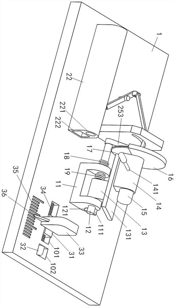
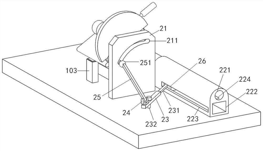
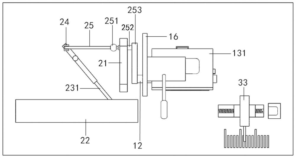
[0026] Depend on Figure 1 to Figure 6 As shown, a stainless steel pipe cutting machine with automatic feeding and auxiliary compression after cutting includes a bottom plate 1, a rotating seat 11 is provided on the top surface of the bottom plate 1, a rotating central shaft 12 is arranged in the rotating seat 11, and a rotating central shaft 12 An inclined connection block 13 is provided on the top surface of the inclined connection block 13. T...


PUM


Abstract

The invention discloses a stainless steel pipe cutting machine capable of automatically feeding and assisting in pressing after cutting. The stainless steel pipe cutting machine is characterized in that an automatic feeding base is arranged on the left side of a cutting blade, a feeding frame is arranged in the automatic feeding base in a sliding mode, the feeding frame is connected with a rotating center shaft in a rotating base through a connecting rod mechanism, and a vacuum suction cup and a pressing block are arranged on the feeding frame; when the cutting blade approaches a stainless steel pipe, the pressing block ascends and abuts against the outer circle wall of the stainless steel pipe, when the cutting blade cuts the stainless steel pipe, the pressing block stops ascending, and when the cutting blade finishes cutting reset, the vacuum suction cup adsorbs and drives the stainless steel pipe to move. The stainless steel pipe cutting machine has the advantages that by arrangingthe connecting rod mechanism, the feeding frame can drive the stainless steel pipe to conduct automatic feeding after the cutting machine completes cutting, in addition, the pressing block can automatically rise and press against the bottom of the stainless steel pipe when the cutting machine conducts cutting, the stainless steel pipe is fixed, the automation degree is high, and the cutting efficiency and quality are greatly improved.

Description

Technical field: [0001] The invention relates to the technical field of stainless steel pipe processing equipment, in particular to a stainless steel pipe cutting machine with automatic feeding and auxiliary pressing after cutting. Background technique: [0002] There are many applications of stainless steel pipes in daily life, such as anti-theft windows, guardrails, etc. The most common way of processing is manual circular cutting machine, which cuts a long stainless steel pipe into small sections of different lengths, but in each After each cutting, the stainless steel pipe needs to be moved forward for the next cutting, which is time-consuming and labor-intensive. In addition, in order to prevent the stainless steel pipe from rotating or moving during cutting, the stainless steel pipe needs to be properly fixed. The existing method is to directly Holding the other end of the stainless steel tube is neither stable nor safe. Contents of the invention [0003] The object...

Claims


Application Information

Patent Timeline
IPC IPC(8): B23D21/00B23Q7/00B23Q3/06
CPCB23D21/00B23Q3/064B23Q7/00
Inventor 丁佳伟
Owner 永康市明科自动化设备有限公司
Learn More