Hard alloy shaft sleeve batch plane grinding clamp

A technology of hard alloy and shaft sleeves, which is applied in the direction of grinding drive devices, grinding machines, manufacturing tools, etc., can solve problems such as difficult blanking and conveying operations, low work efficiency, and difficult batch processing of hard alloy shaft sleeves. To achieve the effect of improving stability

Active Publication Date: 2020-10-02
JIANGSU YITONG FLUID TECH
View PDF8 Cites 4 Cited by
  • Summary
  • Abstract
  • Description
  • Claims
  • Application Information

AI Technical Summary

Problems solved by technology

[0004] The purpose of the present invention is to provide a batch surface grinding fixture for cemented carbide bushings, to solve the problem that the existing plane grinding fixtures proposed in the above background tec

Method used


Image

  • Hard alloy shaft sleeve batch plane grinding clamp
  • Hard alloy shaft sleeve batch plane grinding clamp
  • Hard alloy shaft sleeve batch plane grinding clamp

Examples


Embodiment Construction

[0027] The following will clearly and completely describe the technical solutions in the embodiments of the present invention with reference to the accompanying drawings in the embodiments of the present invention. Obviously, the described embodiments are only some, not all, embodiments of the present invention. Based on the embodiments of the present invention, all other embodiments obtained by persons of ordinary skill in the art without making creative efforts belong to the protection scope of the present invention.

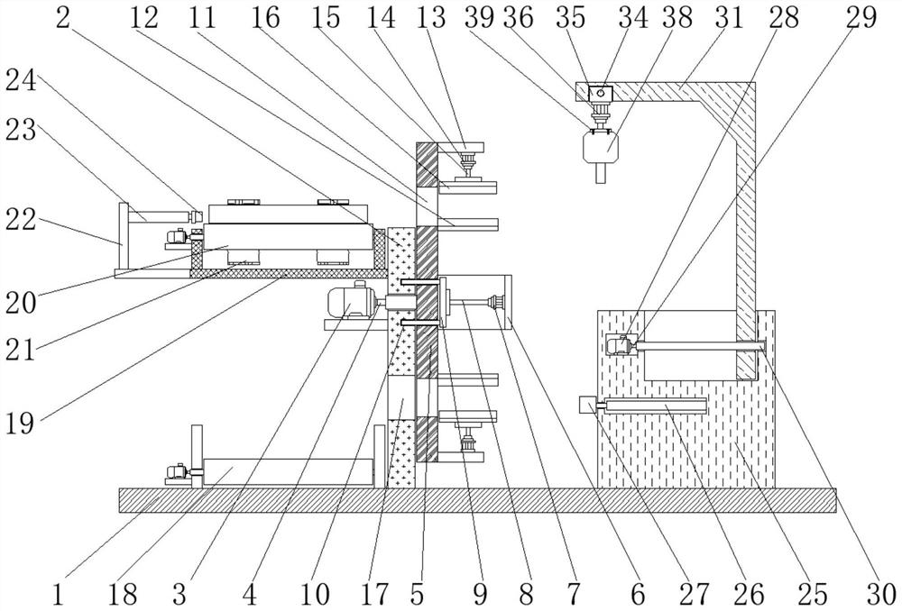
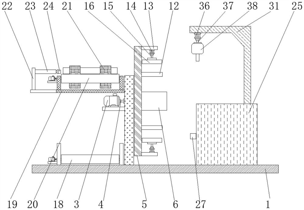
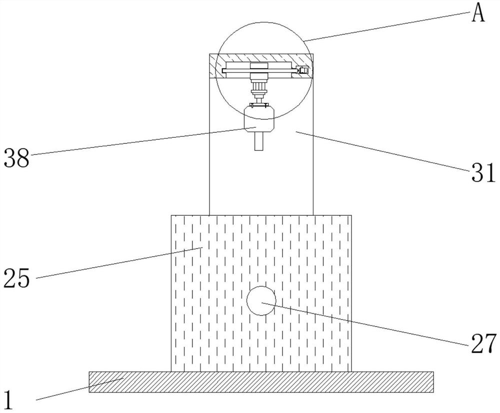
[0028] see Figure 1-6 , the present invention provides a technical solution: a cemented carbide bushing batch surface grinding fixture, according to figure 1 and figure 2 As shown, the upper end surface of the base 1 is fixed with a bracket 2, and the right end surface of the bracket 2 is rotatably connected with a rotating plate 5, the left side of the bracket 2 is fixed with a first motor 3, and the right side of the first motor 3 passes through the first...


PUM


Abstract

The invention discloses a hard alloy shaft sleeve batch plane grinding clamp. The hard alloy shaft sleeve batch plane grinding clamp comprises a base and a second motor, supporting plates are fixed tothe upper side and the lower side of the right end face of a rotating plate correspondingly, a second opening is formed in a support, a first conveying belt device is rotationally connected to the left side of the upper end face of the base, a supporting frame is fixed to the left end face of the top of the support, a fixing frame is fixed to the left side of the supporting frame, a bearing seatis fixed to the right side of the upper end face of the base, a movable frame is slidably connected to the upper end face of the bearing seat, and a third hydraulic cylinder is fixed to the lower endface of the sliding block. According to the hard alloy shaft sleeve batch plane grinding clamp, when a hard alloy shaft sleeve moves to the right side of a first push block, a second conveying belt device stops rotating, the first push block moves rightwards and pushes the hard alloy shaft sleeve to the positions between a corresponding fixed clamping sleeve and a corresponding movable clamping sleeve, and then the corresponding movable clamping sleeve moves towards the inner side to clamp and fix the hard alloy shaft sleeve, so that the stability of the hard alloy shaft sleeve is convenientlyimproved.

Description

technical field [0001] The invention relates to the related technical field of cemented carbide bushings, in particular to a fixture for batch plane grinding of cemented carbide bushings. Background technique [0002] The shaft sleeve is a cylindrical mechanical part that is set on the rotating shaft. It is an integral part of the sliding bearing. Generally speaking, the shaft sleeve and the bearing seat adopt an interference fit, while the shaft adopts a clearance fit, and the cemented carbide shaft sleeve series products , with high temperature resistance, corrosion resistance, wear resistance and other excellent properties, it is widely used in modern production and manufacturing industries, especially the core working parts of some special working extreme environments, such as oil and gas, automobile ships, steel mines and other large-scale industrial production , the good performance and long service life of the cemented carbide bushing are an effective form of improvin...

Claims


Application Information

Patent Timeline
IPC IPC(8): B24B19/00B24B41/00B24B41/04B24B41/06B24B47/20B24B47/22
CPCB24B19/00B24B41/005B24B41/04B24B41/06B24B47/20B24B47/22
Inventor 王杰夏伟夏欣龙
Owner JIANGSU YITONG FLUID TECH
Why Eureka
Try Eureka