Adjustable ceramic tile cutter for architectural decoration

A cutter and ceramic tile technology, which is applied in construction, building construction, work accessories, etc., can solve the problems of low cutting accuracy and safety, and achieve the effect of saving materials, avoiding waste, and avoiding tile cracking.

Active Publication Date: 2020-10-02
BEIJING UNI CONSTR DECORATION CO LTD
View PDF8 Cites 0 Cited by
  • Summary
  • Abstract
  • Description
  • Claims
  • Application Information

AI Technical Summary

Problems solved by technology

[0005] In order to overcome the current need for cutting in the decoration process, the decoration workers often draw the line first and then use the cutting machine to manually cut along the path of the line, which has the disadvantages of low cutting accuracy and safety problems. The technical problem is: to provide a practical Adjustable ceramic tile cutter for building decoration with strong performance, good safety and high cutting precision

Method used


Image

  • Adjustable ceramic tile cutter for architectural decoration
  • Adjustable ceramic tile cutter for architectural decoration
  • Adjustable ceramic tile cutter for architectural decoration

Examples


Embodiment 1

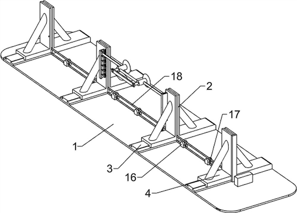
[0024] A tile adjustable cutter for building decoration, such as Figure 1-4 As shown, it includes a bottom plate 1, a fixed L-shaped top plate 2, a straight slide rail 3, a movable L-shaped top plate 4, a mobile cutting device 5 and an adjustment mechanism 6, and four fixed L-shaped top plates 2 are evenly spaced on the rear side of the top of the bottom plate 1. Four straight slide rails 3 are evenly spaced on the front side of the top of the base plate 1, and a movable L-shaped top plate 4 is slidably arranged on the straight slide rails 3. The fixed L-shaped top plate 2 cooperates with the movable L-shaped top plate 4, and the bottom plate 1 is provided with The mobile cutting device 5 is located above the fixed L-shaped top board 2 and the movable L-shaped top board 4 , and an adjustment mechanism 6 is arranged between the bottom board 1 and the mobile cutting device 5 .

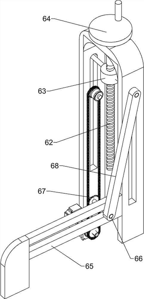
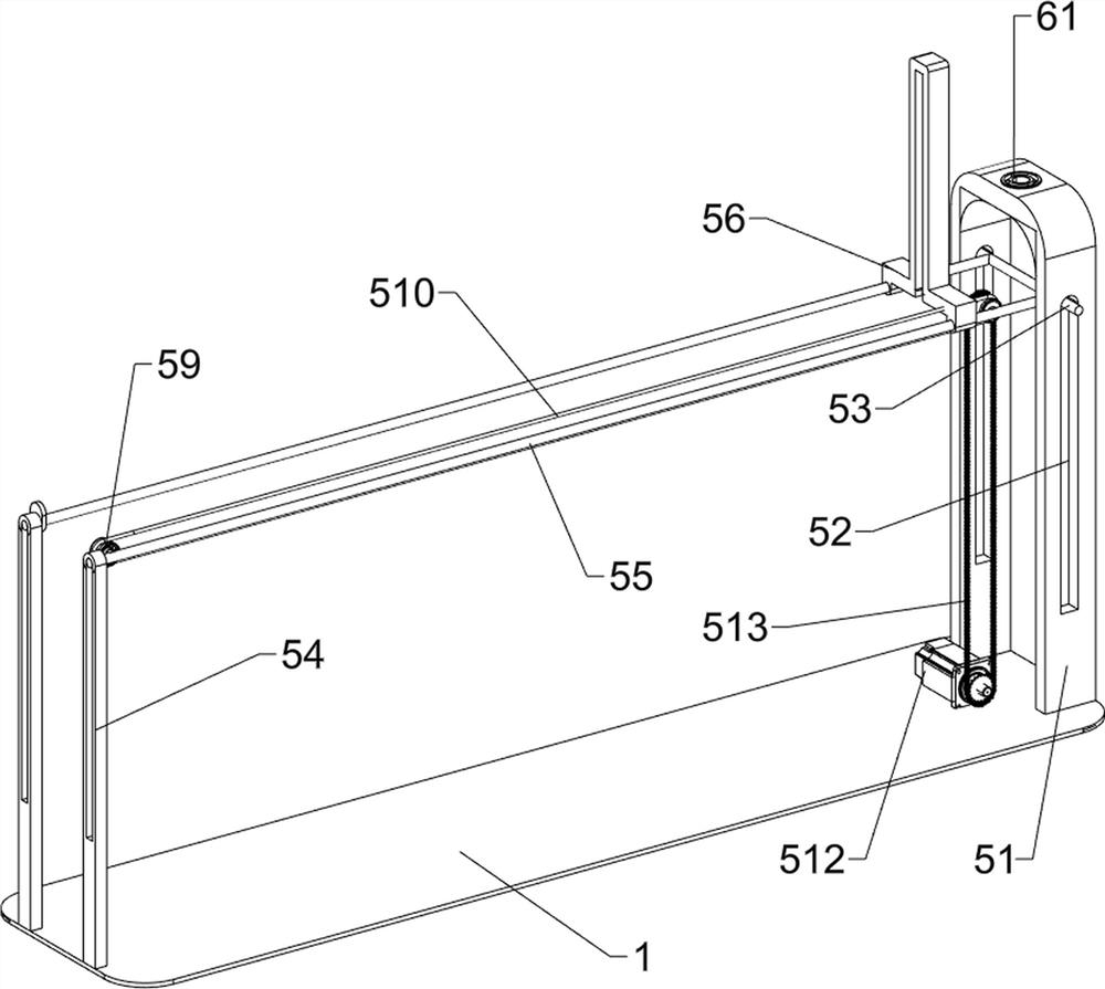
[0025] Mobile cutting device 5 includes N-shaped plate 51, slide bar 53, guide plate 54, guide rod 5...

Embodiment 2

[0029] On the basis of Example 1, such as Figure 5-7 As shown, it also includes a straight guide plate 7, a sliding rod 8, a suction cup cylinder 9, a connecting rod 10, a piston 11, a pull rod 12, a pawl 13, an elastic member 14 and a stopper 15, and the two movable L-shaped The top plate 4 is symmetrically arranged with straight guide plates 7, the two straight guide plates 7 are slidingly equipped with slide rods 8, the inner ends of the two slide rods 8 are provided with suction cup cylinders 9, and a connecting rod is provided between the two suction cup cylinders 9. Rod 10, piston 11 is arranged slidingly in two sucker cylinders 9, piston 11 cooperates with sucker cylinder 9, a pull rod 12 is arranged between two pistons 11, and two straight guide plates 7 are provided with spines evenly spaced on the opposite sides and rear sides. An elastic member 14 is arranged between the pawl 13 and the ratchet 13 and the straight guide plate 7 , and stoppers 15 are arranged on the...


PUM


Abstract

The invention relates to a cutter, in particular to an adjustable ceramic tile cutter for architectural decoration. The adjustable ceramic tile cutter for architectural decoration is high in practicability, safety and cutting precision and comprises a baseboard, linear slide rails, movable L-shaped top plates and a movable cutting device, wherein fixed L-shaped top plates are uniformly spaced at one side of the baseboard, the linear slide rails are uniformly spaced at the side, opposite to the fixed L-shaped top plates, of the baseboard, the movable L-shaped top plates are slidably arranged onthe linear slide rails, and the movable cutting device is arranged on the baseboard and is located above the fixed L-shaped top plates and the movable L-shaped top plates. When the cutter is utilized, a flat belt and an N-shaped frame push the cutter to cut ceramic tiles, a rocker adjusts the position of a nut through a lead screw, then the cutting size is determined, in this way, the ceramic tiles can be precisely cut, inaccuracy caused by manual cutting is avoided, and then materials are saved.

Description

technical field [0001] The invention relates to a cutter, in particular to an adjustable tile cutter for building decoration. Background technique [0002] The history of tiles can be traced back to BC, and now the use of tiles has been prevalent all over the world. In the history of tiles, mosaics in Spain and Portugal, floor tiles in the Italian Renaissance, glazed tiles in Antwerp, the development of tile illustrations in the Netherlands, and Germany The tiles are all milestones. Nowadays, all over the world, automated production technology is used, and human hands are only used to operate equipment. As in the past, tiles are used both inside and out. [0003] When using tiles to decorate your own house, it is inevitable to cut the tiles, but there are many problems in tile cutting. The thinner and shallower the knife marks, the more straight and beautiful the brick edge after the tiles are cracked. On the contrary, the more the knife marks are The deeper the rougher t...

Claims


Application Information

Patent Timeline
IPC IPC(8): B28D1/22B28D7/00B28D7/04E04F21/00
CPCB28D1/22B28D7/00B28D7/04E04F21/00Y02P70/10
Inventor 陈来
Owner BEIJING UNI CONSTR DECORATION CO LTD
Why Eureka
Try Eureka