Double-air-duct air outlet structure of automobile air conditioner

A technology of automobile air conditioner and tuyere structure, which is applied to vehicle components, air handling equipment, heating/cooling equipment, etc., which can solve the problems of poor blowing effect, small blowing angle, and increased project development difficulty, so as to achieve good blowing effect and blowing air wide range of effects

Active Publication Date: 2020-10-02
NINGBO JOYSONQUIN AUTOMOTIVE SYST HLDG CO LTD
View PDF8 Cites 6 Cited by
  • Summary
  • Abstract
  • Description
  • Claims
  • Application Information

AI Technical Summary

Problems solved by technology

[0003] At present, most of the car air outlets on the market are controlled by a variety of separate mechanisms or multiple motors to control the air volume and wind direction of the car air outlet. The result of the separation of the mechanisms is that it requires multiple external parts to operate or increase the number of motors. The air guide function of the car air outlet not only requires complex A-side requirements of the car interior and the addition of various control units, but also increases the difficulty of project development. At the same time, the increase in the number of control units or motors also increases the cost of project development. In addition, the current market Hidden or narrow air outlets are popular in the world. However, the air outlets have strict requirements on the air outlet angle. The wind direction needs to cover the range from the eyes of the driver and passengers to the lower abdomen from top to bottom, which is limited by the narrow air outlet. Opening, the blowing angle is small, and the blowing effect is not good

Method used


Image

  • Double-air-duct air outlet structure of automobile air conditioner
  • Double-air-duct air outlet structure of automobile air conditioner
  • Double-air-duct air outlet structure of automobile air conditioner

Examples


Embodiment Construction

[0025] The present invention is further explained in conjunction with the accompanying drawings.

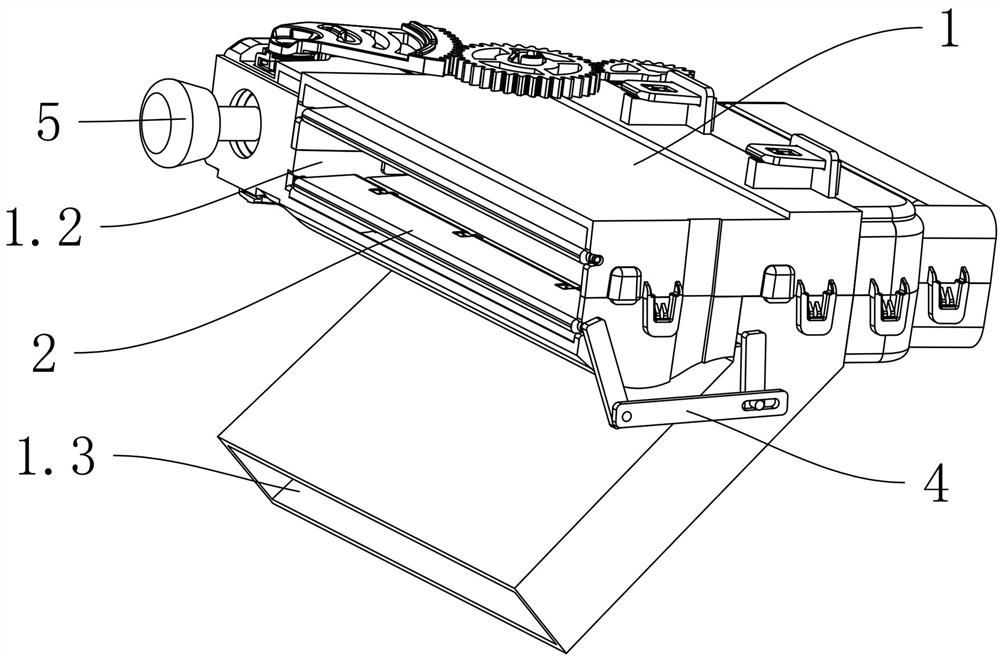
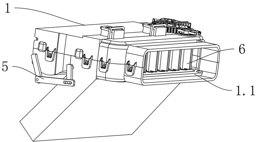
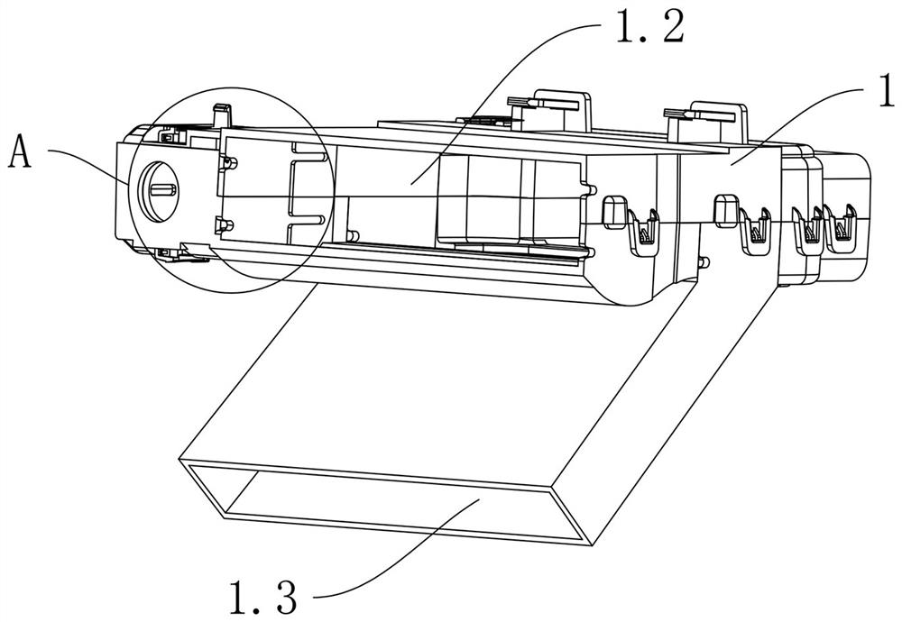
[0026] see Figure 1 to Figure 7 The shown dual air duct air outlet structure of an automobile air conditioner includes a housing 1 and an air guiding mechanism. The housing 1 has an air inlet section 1.1 and a lower air outlet duct 1.3 communicating with the air inlet section 1.1 and The upper air outlet 1.2, the upper air outlet 1.2 and the lower air outlet 1.3 are facing different positions, and the air guide mechanism includes the main wind vane 2 located in the upper air outlet 1.2 and the upper air outlet 1.2 located in the upper air outlet 1.2. and the channel baffle plate 3 between the lower air outlet channel 1.3, the main wind blade 2 and the channel baffle plate 3 are respectively rotated and arranged in the housing 1, and the said main wind blade 2 is rotated and arranged in the upper air outlet channel 1.2 for adjustment For the wind direction in the upper air outle...


PUM


Abstract

The invention discloses a double-air-duct air outlet structure of an automobile air conditioner. The double-air-duct air outlet structure comprises a shell and an air guide mechanism, the shell is provided with an air inlet section, a lower air outlet channel and an upper air outlet channel, the air guide mechanism comprises a main air guide blade located in the upper air outlet channel and a channel baffle located between the upper air outlet channel and the lower air outlet channel, and the main air guide blade is in linkage with the channel baffle through an intermittent linkage mechanism;when the main air guide blade rotates upwards from the initial position to conduct longitudinal air guide adjustment, the channel baffle seals the lower air outlet channel, and the main air guide blade rotates relative to the channel baffle through the intermittent linkage mechanism. When the main air guide blades rotate downwards from the initial position to conduct longitudinal air guide adjustment, the main air guide blades drive the channel baffle to rotate upwards through the intermittent linkage mechanism. The double-air-duct structure is arranged so that the air blowing range is large,and the air blowing effect is good.

Description

technical field [0001] The invention relates to the technical field of auto parts, in particular to a dual air duct air outlet structure of an auto air conditioner. Background technique [0002] The air outlet of the car air conditioner is one of the necessary parts of the car. In order to meet the temperature requirements of drivers of different heights, different shapes, and different habits, the air outlet of the car air conditioner on the market is generally used to control the upper blades, lower blades, dampers and other components. To achieve wind direction adjustment. [0003] At present, most of the car air outlets on the market are controlled by a variety of separate mechanisms or multiple motors to control the air volume and wind direction of the car air outlet. The result of the separation of the mechanisms is that it requires multiple external parts to operate or increase the number of motors. The air guide function of the car air outlet not only requires compl...

Claims


Application Information

Patent Timeline
Patent Type & Authority Applications(China)
IPC IPC(8): B60H1/34
CPCB60H1/34B60H1/3414B60H2001/3471
Inventor 尹剑钦俞江涛陈李杰张强寅
Owner NINGBO JOYSONQUIN AUTOMOTIVE SYST HLDG CO LTD
Why Eureka
Try Eureka