[0045] The following will be combined with Figure 1-Figure 18 The present invention is described in detail, and the technical solutions in the embodiments of the present invention are clearly and completely described. Apparently, the described embodiments are only some of the embodiments of the present invention, not all of them. Based on the embodiments of the present invention, all other embodiments obtained by persons of ordinary skill in the art without making creative efforts belong to the protection scope of the present invention.
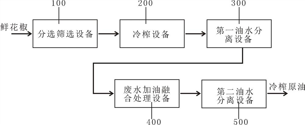
[0046] The present invention provides a Chinese prickly ash oil preparation system through improvement. The system includes sorting and screening equipment 100, pressing equipment 200, first oil-water separation equipment 300, waste water refueling fusion treatment equipment 400, and second oil-water separation equipment 500; sorting The screening equipment 100, the squeezing equipment 200, the first oil-water separation equipment 300, the waste water refueling fusion treatment equipment 400, and the second oil-water separation equipment 500 are respectively connected in sequence to form the preparation system.
[0047]In the pepper oil preparation system of the present invention, the squeezing device 200 includes a casing 201, a first squeezing chamber 204 is arranged in the casing 201, and a pair of male and female screw shafts 203 are arranged in the first squeezing chamber 204, Both ends of the yin and yang screw shaft 203 are kept in rotational connection with the side wall of the first press chamber 204 through bearings; a motor 208 is fixedly installed in the housing 201, and the rotating shaft of the motor 208 is connected with the yin and yang screw shaft 203, and one end of the yin and yang screw shaft 203 is installed with a belt wheel A211; a second squeeze chamber 209 and a third squeeze chamber 210 are arranged in the housing 201, and the first squeeze chamber 204 communicates with the second squeeze chamber 209 and the third squeeze chamber 210 through a pipeline 205; An oil leakage groove 216 is fixedly installed on the bottom surface of the squeeze chamber 209 and the third squeeze chamber 210, and the oil leakage groove 216 communicates with the oil outlet 206; the ends of the second squeeze chamber 209 and the third squeeze chamber 210 have a , communicated with the slag outlet pipe 207.
[0048] A feed port 202 is provided at the opening of the upper end of the first press chamber 204, a rectangular hole is opened at the connection between the housing 201 and the feed port 202, and the feed port 202 extends out of the housing 201 through the rectangular hole;
[0049] A second screw shaft is arranged in the second squeeze chamber 209, and a pulley B212 is installed at one end of the second screw shaft. Similarly, a third screw shaft is arranged in the third squeeze chamber 210, and the third screw shaft A pulley C213 is installed at one end of the shaft;
[0050] The walls of the second squeeze chamber 209 and the third squeeze chamber 210 are covered with mesh holes, the pulley A211 is rotatably connected to the pulley B212 through the belt B215, and the pulley B212 is rotatably connected to the pulley C213 through the belt A214.
[0051] A sieve plate 217 is set in the oil leakage tank 216; the pipeline 205 is divided into sub-pipelines A205.1 and sub-pipelines B205.2 through a partition, and the sub-pipelines A205.1 communicate with the second press chamber 209, the The subpipe B205.2 communicates with the third press chamber 210 .
[0052] When the present invention is implemented, the Chinese prickly ash is fed through the feed port 202, and the Chinese prickly ash enters the first pressing chamber 204, and the yin and yang screw shaft 203 presses it for the first time, and after being diverted by the pipeline 205, it enters the second pressing chamber 209 and the The third squeeze chamber 210 is pressed for the second time, the pepper oil passes through the mesh, and after the second filtration through the sieve plate 217, it leaks into the oil leakage groove 216, and finally flows out through the oil outlet 207, and the oil residue is driven by the screw from the The slag outlet 206 is discharged. The door panel is reasonably designed. A door panel is arranged on the front of the casing, which is hinged with the casing through a hinge. A handle is installed on the outside of the door panel. When the door panel is opened, the interior of the device can be repaired and cleaned, which is convenient. The sieve plate is reasonably designed, and a sieve plate is arranged in the oil leakage tank, and the pepper essential oil is filtered twice through the sieve plate, so that the pepper oil is more clarified. After the pepper is pressed through the first pressing chamber, the flow is diverted through the pipeline, and then enters the second pressing chamber and the third pressing chamber respectively for pressing, which not only improves the oil yield, but also improves the pressing efficiency.
[0053] In a pepper oil preparation system according to the present invention, the first oil-water separation device 300 and the second oil-water separation device 500 both adopt the following structure;
[0054] The separation device includes a casing 301, two sets of universal wheels 301.1 are fixedly installed at the four corners of the lower end surface of the casing 301, a door panel 301.2 is arranged on the top of the casing 301, and the door panel 301.2 is hinged with the casing 301 through a hinge 301.4. A mounting plate 306 is arranged in the lower part of 301, and the mounting plate 306 is fixedly connected with the shell 301;
[0055] A motor 305 is arranged in the casing 301 and fixedly installed on the upper end surface of the mounting plate 306, and the rotating shaft of the motor 305 is equipped with a pulley B312;
[0056] An outer cylinder 302 is arranged in the housing 301 and is fixedly installed on the upper end surface of the mounting plate 306. A hole is opened on the lower end surface of the outer cylinder 302 and communicated with a pipe 307;
[0057] An inner cylinder 303 is placed in the outer cylinder 302, a rotating shaft 313 is fixedly installed on the lower end surface, the rotating shaft 313 is rotationally connected with the outer cylinder 302 through a bearing, and a pulley A310 is installed at the end;
[0058] The pulley A310 is connected to the pulley B312 through a belt 311 in rotation;
[0059] An inner tank 304 is placed in the inner cylinder 303 and is in flexible connection with the inner cylinder 303 .
[0060] The upper end of the door panel 301.2 has a hole connected to a feed port 301.3, and a handle 301.5 is installed on the upper end of the door panel 301.2;
[0061] The inner tank 304 is cylindrical, the side wall is covered with mesh holes, two pairs of T-shaped blocks 304.1 are fixedly connected to the top of the outer wall, and a rectangular groove is opened at the connection between the inner cylinder 303 and the T-shaped block 304.1, and the T-shaped block The narrow part of 304.1 matches the rectangular groove; the side wall of the inner cylinder 303 is covered with mesh holes.
[0062] A flow valve 308 is arranged at the outlet of the pipeline 307, the inlet of the flow valve 308 is communicated with the outlet of the pipeline 307, and the outlet is communicated with a discharge pipe 309, the connection between the shell 301 and the discharge pipe 309 is perforated, and the discharge pipe 309 protrudes from housing 301 through the hole.
[0063] When the present invention is implemented, the unseparated pepper oil is introduced through the feed port 301.3, the motor 305 drives the inner cylinder 303 to rotate, the inner tank 304 rotates with the inner cylinder, the pepper oil is separated into the outer cylinder 302, and flows out through the pipeline 307, and the control The flow valve 308 changes the flow rate of pepper oil.
[0064] The inner cylinder is reasonably designed, the inner cylinder is placed in the outer cylinder, and a rotating shaft is fixedly installed on the lower end surface. The rotating shaft is connected to the outer cylinder through bearings, and a pulley A is installed at the end. The pulley A is connected to the belt Wheel B is connected by belt rotation, and the motor drives the inner cylinder to rotate to separate the pepper oil and flow out through the pipe on the lower end of the outer cylinder, which improves the separation efficiency of pepper oil and reduces the work intensity.
[0065] The inner tank is reasonably designed, the inner tank is placed in the inner cylinder, and is connected with the inner cylinder in a flexible manner. , the inner tank is cylindrical, the side wall is covered with mesh holes, two pairs of T-shaped blocks are fixedly connected to the top of the outer wall, a rectangular groove is opened at the connection between the inner cylinder and the T-shaped block, and the narrow part of the T-shaped block Cooperate with the rectangular groove, the liner rotates with the inner cylinder, the pepper oil in the liner is separated, the pepper stays in the liner, when the liner is taken out, the pepper can be poured out, which is convenient for cleaning and operation.
[0066] A flow valve is reasonably designed, and a flow valve is set at the outlet of the pipeline. The inlet of the flow valve is connected to the outlet of the pipeline, and the outlet is connected to a discharge pipe. The connection between the shell and the discharge pipe is opened, and the discharge pipe passes through The hole extends out of the shell, and the separated pepper oil flows out through the discharge pipe, and the flow valve controls the flow, which is convenient for the staff to replace the oil receiving barrel. If it is not replaced for a long time, the pepper oil will not overflow, resulting in waste.