Electroplating hanger

An electroplating hanger and hanger technology, applied in the electrolysis process, electrolysis components and other directions, can solve the problems of single function, simple structure, low electroplating efficiency, etc., and achieve the effect of convenient movement and easy hanging.

Pending Publication Date: 2020-10-02
黄冬冬
View PDF7 Cites 5 Cited by
  • Summary
  • Abstract
  • Description
  • Claims
  • Application Information

AI Technical Summary

Problems solved by technology

The existing electroplating hanger has a simple structure and a single function, and the distance between the hooks is fixed and cannot be adjusted. As a result, when the hanger hangs workpieces of different sizes, it cannot adjust the distance between the hooks according to the workpieces of different sizes. The spacing is adjusted so that during electroplating, if it is necessary to hang workpieces of different sizes, the pendant needs to be replaced, and the replacement of the hanger is time-consuming and laborious, which greatly reduces the efficiency of electroplating

Method used


Image

  • Electroplating hanger
  • Electroplating hanger
  • Electroplating hanger

Examples


Embodiment Construction

[0022] In order to make the technical means, creative features, goals and effects achieved by the present invention easy to understand, the present invention will be further described below in conjunction with specific embodiments.

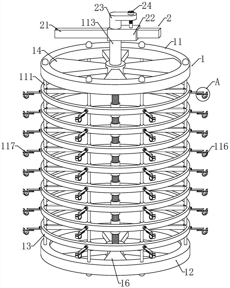
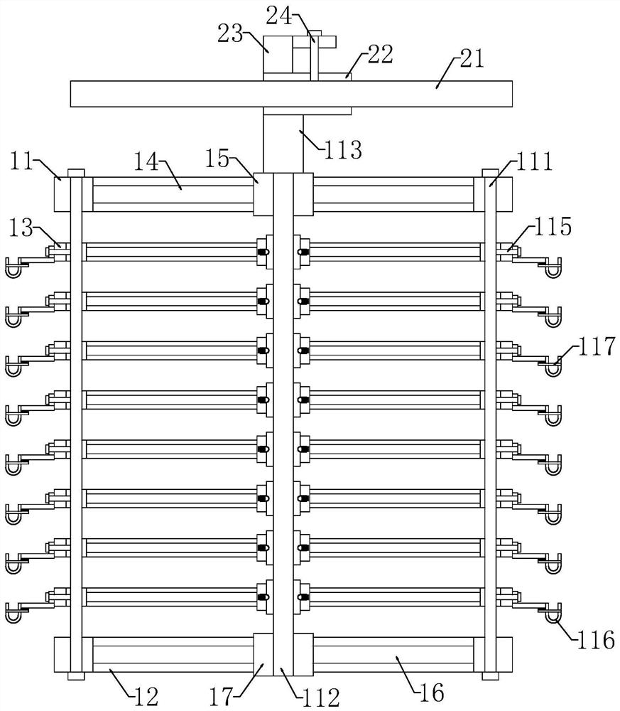
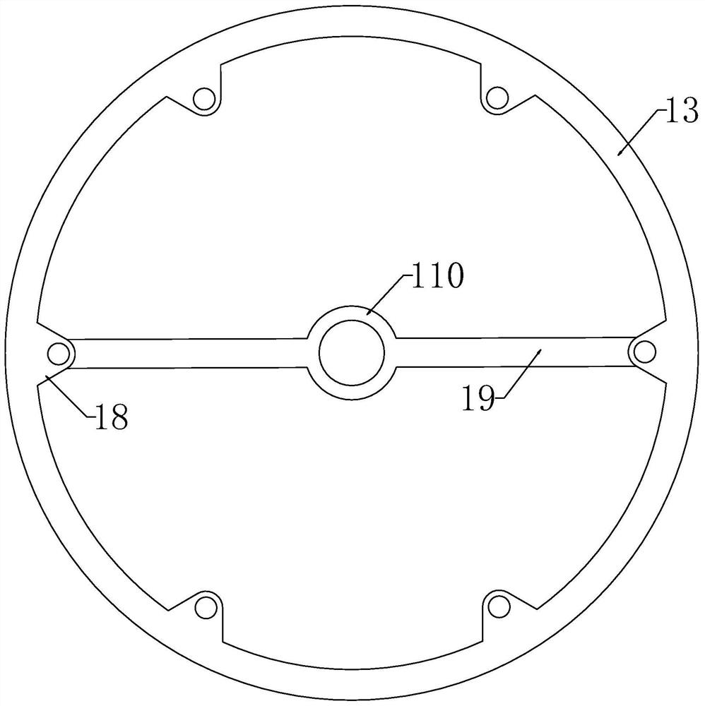
[0023] Such as Figure 1-Figure 7As shown, an electroplating hanger according to the present invention includes a hanger assembly 1, a moving assembly 2 and a locking assembly 3, the moving assembly 2 is arranged above the hanger assembly 1, and the locking assembly 3 is arranged on the hanging assembly The inside of the hanger assembly 1; the hanger assembly 1 includes an upper hanging ring 11, a lower hanging ring 12, a support ring 13, a first connecting rod 14, a first rotating sleeve 15, a second connecting rod 16, a second rotating sleeve Tube 17, connecting block 18, third connecting rod 19, third rotating sleeve 110, slide bar 111, screw mandrel 112, servo motor 113, hanging plate 114 and first locking bolt 115, the upper hanging ring 11 ...


PUM


Abstract

The invention relates to the field of electroplating hangers, in particular to an electroplating hanger. The electroplating hanger comprises a hanger assembly, a moving assembly and a locking assembly, the moving assembly is arranged above the hanger assembly, and the locking assembly is arranged in the hanger assembly. A sliding sleeve sliding along a guide rail and the guide rail can be limitedthrough a second locking bolt penetrating through a through hole, due to the fact that limiting of the sliding sleeve can be achieved only by rotating the second locking bolt, the hanger is quite convenient to move, and when workpieces of different sizes need to be hung, only a servo motor needs to be started, the output end of the servo motor drives a lead screw to rotate through a coupler, the lead screw can drive an internal thread sleeve connected to the rod wall in a threaded and sleeving mode to ascend and descend when rotating, a third rotating sleeve on the outer sleeve wall of the internal thread sleeve can be connected with an inserting block to enable the third rotating sleeve to ascend and descend along with ascending and descending of the internal thread sleeve, and the thirdrotating sleeve can drive a supporting ring to ascend and descend during ascending and descending.

Description

technical field [0001] The invention relates to the field of electroplating racks, in particular to an electroplating rack. Background technique [0002] Electroplating is the process of plating a thin layer of other metals or alloys on the surface of certain metals using the principle of electrolysis. It is a process of using electrolysis to attach a layer of metal film to the surface of metal or other material parts to prevent metal oxidation ( Such as rust), improve wear resistance, electrical conductivity, reflective properties, corrosion resistance (copper sulfate, etc.) and enhance the appearance. According to the shape of the parts, the technical requirements of the coating, the electroplating process and the size of the equipment, there are different types of hangers. The existing electroplating hanger has a simple structure and a single function, and the distance between the hooks is fixed and cannot be adjusted. As a result, when the hanger hangs workpieces of dif...

Claims


Application Information

Patent Timeline
Patent Type & Authority Applications(China)
IPC IPC(8): C25D17/08
CPCC25D17/08
Inventor 黄冬冬李云
Owner 黄冬冬
Why Eureka
Try Eureka