Firefighting exhaust fan

A smoke exhaust fan and fire-fighting technology, which is applied in the direction of electromechanical devices, mechanical equipment, and control of mechanical energy, can solve problems such as troublesome operation

Active Publication Date: 2020-10-02
三森空调集团有限公司
View PDF9 Cites 7 Cited by
  • Summary
  • Abstract
  • Description
  • Claims
  • Application Information

AI Technical Summary

Problems solved by technology

However, when the device needs to change the exhaust air volume, the exhaust pipe needs to be removed, which is troublesome to operate

Method used


Image

  • Firefighting exhaust fan
  • Firefighting exhaust fan
  • Firefighting exhaust fan

Examples


specific Embodiment approach 1

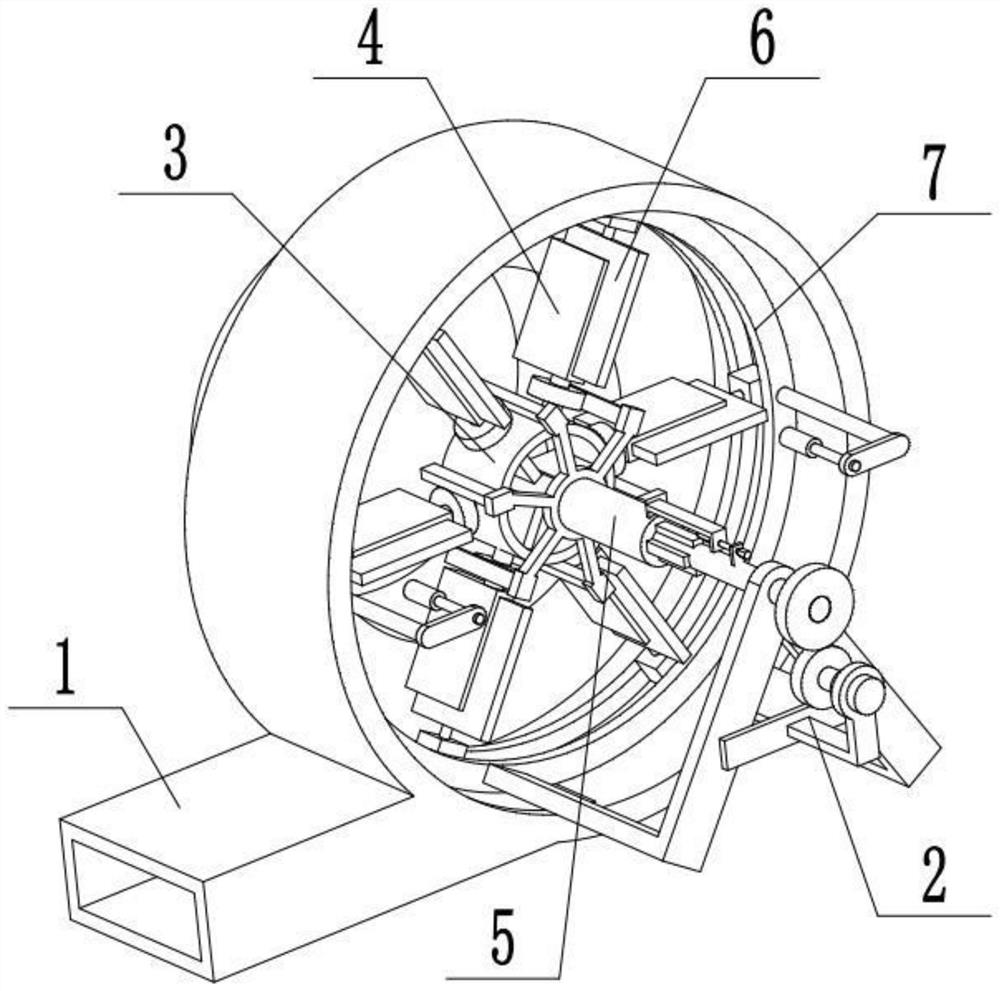
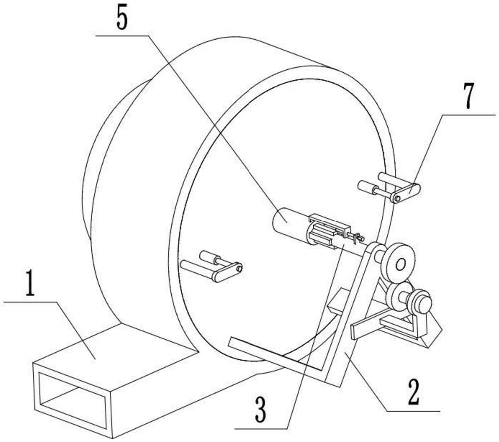
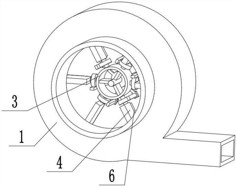
[0027] Combine below Figure 1-7 Describe this embodiment, a fire-fighting smoke exhaust fan, including a housing 1, a driving device 2, a blade rotation control mechanism 3, an inner blade assembly opening 4, an angle adjustment member 5, an outer blade assembly 6, and a telescopic adjustment mechanism 7 , the drive device 2 is fixedly connected to the outer end of the housing 1, one end of the blade rotation control mechanism 3 is connected to the drive device 2, and the other end of the blade rotation control mechanism 3 is located in the housing 1, a plurality of The inner fan blade assembly port 4 is evenly arranged on the fan blade rotation control mechanism 3, and the angle adjustment member 5 is cooperatively connected to the fan blade rotation control mechanism 3, and the angle adjustment member 5 is cooperatively connected with a plurality of inner fan blade assembly ports 4. Each outer blade assembly 6 is movably connected with a plurality of inner blade assembly op...

specific Embodiment approach 2

[0029] Combine below Figure 1-7 To illustrate this embodiment, the housing 1 is provided with an air inlet 1-1, an air outlet 1-2 and a front cover 1-3; one end of the housing 1 is provided with an air inlet 1-1, and the housing 1 The lower end is provided with an air outlet 1-2, the front end of the housing 1 is detachably connected to the front cover 1-3, and the driving device 2 is fixedly connected to the front cover 1-3. When in use, a plurality of inner fan blade assembly ports 4 and a plurality of outer fan blade assemblies 6 rotate to generate negative pressure in the casing 1, and the smoke is sucked into the casing 1 through the air inlet 1-1, and is discharged from the air outlet 1-2. discharge.

specific Embodiment approach 3

[0031] Combine below Figure 1-7Describe this embodiment, described driving device 2 comprises motor 2-1, fixed frame 2-2 and first gear 2-3; Motor 2-1 is fixedly connected on the fixed frame 2-2 by motor frame, -2 is fixedly connected to the front cover plate 1-3, the output shaft of the motor 2-1 is fixedly connected to the first gear 2-3, and the first gear 2-3 is connected with the blade rotation control mechanism 3 in cooperation. When in use, the motor 2-1 starts to drive the first gear 2-3 to rotate, and the first gear 2-3 drives the fan blade rotation control mechanism 3 to rotate.


PUM


Abstract

The invention discloses a firefighting exhaust fan and relates to the technical field of ventilation equipment. The firefighting exhaust fan comprises a shell, a driving device, a fan blade rotary control mechanism, a plurality of internal fan blade component openings, an angle adjusting piece, a plurality of external fan blade components and a telescopic adjusting mechanism. The firefighting exhaust fan has the beneficial technical effect of directly changing the air draft quantity without being detached; the driving device is fixedly connected with the external end of the shell; one end of the fan blade rotary control mechanism is connected onto the driving device in a matching manner; the other end of the fan blade rotary control mechanism is positioned in the shell; the internal fan blade component openings are uniformly formed in the fan blade rotary control mechanism in a surrounding manner; the angle adjusting piece is connected onto the fan blade rotary control mechanism in a matching manner and is connected with the internal fan blade component openings in a matching manner; the external fan blade components are movably connected with the internal fan blade component openings; the external ends of the external fan blade components are movably connected into the telescopic adjusting mechanism; and the telescopic adjusting mechanism is connected onto the shell in a matching manner.

Description

technical field [0001] The invention relates to the technical field of ventilation equipment, in particular to a fire-fighting smoke exhaust fan. Background technique [0002] The patent number is CN201821668675.3 for a quick-adjusting blade exhaust fan. This utility model discloses a quick-adjusting blade exhaust fan, including a volute, with an air outlet on the side of the volute, and an adjustment port on one end of the volute. An exhaust pipe is installed on the outside of the adjustment port, an air inlet is opened in the exhaust pipe, the first rotating shaft is sleeved on the other side of the volute, a pulley is installed on one end of the first rotating shaft, an impeller is installed on the other end of the first rotating shaft, and an adjusting device is installed on the impeller. The belt pulley drives the impeller to rotate through the first rotating shaft, draws air into the volute from the air inlet, and then discharges it from the air outlet. When it is nece...

Claims


Application Information

Patent Timeline
Patent Type & Authority Applications(China)
IPC IPC(8): F04D25/08F04D29/28F04D29/30F04D27/00F04D29/42H02K7/14H02K7/116
CPCF04D25/08F04D27/002F04D29/282F04D29/287F04D29/30F04D29/4226H02K7/116H02K7/14
Inventor 唐伟军
Owner 三森空调集团有限公司
Why Eureka
Try Eureka