Vibration isolation bearing pedestal utilizing two-stage vibration isolation technology

A bearing seat and bearing support seat technology, applied in the field of machinery, can solve problems such as hazards and large vibration of components, and achieve the effects of strong integration, convenient maintenance and strong versatility

Active Publication Date: 2020-10-02
XIAN TECH UNIV
View PDF9 Cites 2 Cited by
  • Summary
  • Abstract
  • Description
  • Claims
  • Application Information

AI Technical Summary

Problems solved by technology

Vibration isolation equipment is usually added to the part where the machine is in contact with the foundation, or vibration isolation equipment is installed on the main working device and the frame. It will generate large vibration and cause harm

Method used


Image

  • Vibration isolation bearing pedestal utilizing two-stage vibration isolation technology
  • Vibration isolation bearing pedestal utilizing two-stage vibration isolation technology
  • Vibration isolation bearing pedestal utilizing two-stage vibration isolation technology

Examples


Embodiment 1

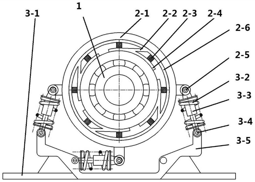
[0031] A vibration isolation bearing seat using secondary vibration isolation technology, such as figure 1 As shown, including the bearing body 1, the bearing fixing ring 2-4, the inner seat fixing ring 2-1 and the base type bearing support seat 3-5, the bearing body 1, the bearing fixing ring 2-4 and the inner seat fixing ring 2-1 is sleeved in order from the inside to the outside, and the bearing fixing ring 2-4 and the inner seat fixing ring 2-1 are connected by a leaf spring 2-2, such as Figure 4 As shown, the structure of the primary leaf spring 2-2 is ring-shaped, the inner wall of the ring is uniformly provided with arc-shaped pieces connected by supporting rods, and the primary damping block 2-3 is bonded between the ring-shaped and the arc-shaped pieces. The inner seat fixing ring 2-1 is provided with connecting ears on both sides and bottom of the circumference, each connecting ear is provided with inner seat fixing ring hinge points 2-5, one end of the secondary damp...

Embodiment 2

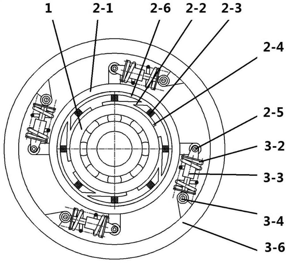
[0034] A vibration isolation bearing seat using secondary vibration isolation technology, such as figure 2 As shown, including the bearing body 1, the bearing fixing ring 2-4, the inner seat fixing ring 2-1 and the circular bearing support seat 3-6, the bearing body 1, the bearing fixing ring 2-4 and the inner seat fixing ring 2-1 is sleeved in order from the inside to the outside, and the bearing fixing ring 2-4 and the inner seat fixing ring 2-1 are connected by a leaf spring 2-2, such as Figure 4 As shown; the structure of the primary leaf spring 2-2 is ring-shaped, the inner wall of the ring is uniformly provided with arc-shaped pieces connected by supporting rods, and the primary damping block 2-3 is bonded between the ring-shaped and the arc-shaped pieces. The inner seat fixing ring 2-1 is provided with 4 connecting ears evenly distributed on the circumference, and each connecting ear is provided with a base hinge point 3-4. One end of the secondary damper 3-3 is hinged ...


PUM


Abstract

The invention belongs to the field of machinery, and particularly relates to a vibration isolation bearing pedestal utilizing a two-stage vibration isolation technology. The vibration isolation bearing pedestal utilizing the two-stage vibration isolation technology provides multi-directional vibration isolation for a rotating part, is directly installed on a vibration source, conducts direct vibration isolation on the vibration source and does not adopt the mode that vibration isolation of an existing facility is located between a foundation and the whole facility. According to the technical scheme, the vibration isolation bearing pedestal utilizing the two-stage vibration isolation technology comprises a bearing body and further comprises a bearing fixing ring, an inner base fixing ring and a bearing supporting base. The bearing body, the bearing fixing ring and the inner base fixing ring are arranged in a sleeving mode in sequence from inside to outside. The bearing fixing ring and the inner base fixing ring are connected through primary vibration isolation devices. The inner base fixing ring and the bearing supporting base are connected through secondary vibration isolation devices. A primary leaf spring outer ring is arranged on an inner ring of the inner base fixing ring.

Description

Technical field [0001] The patent of the invention belongs to the field of machinery, and specifically relates to a vibration isolation bearing seat using secondary vibration isolation technology. Background technique [0002] Bearings are standard parts widely used in the support of rotating parts in various mechanical products; bearing seats are used to fix, support and position the bearings. [0003] Except for some machines that use vibration to work, vibration is harmful to the machine. Vibration can cause structural loosening, premature fatigue of parts, noise, small-scale earthquakes and other hazards. [0004] Machines with rotating parts will inevitably produce vibrations during work, especially for some harsh working conditions, large resistance and unstable conditions, the resulting vibration is particularly serious. Generally, equipment with severe vibration will have corresponding vibration isolation measures. Vibration isolation equipment is usually added to the part...

Claims


Application Information

Patent Timeline
Patent Type & Authority Applications(China)
IPC IPC(8): F16C27/00
CPCF16C27/00
Inventor 朱霖龙刘雅文王林艳樊亚军陈红
Owner XIAN TECH UNIV
Why Eureka
Try Eureka