Planetary roller screw with decelerating function

A planetary roller and lead screw technology, which is applied to belts/chains/gears, mechanical equipment, transmission devices, etc., can solve problems such as reduced load-carrying capacity, increased wear of screw and rollers, and smaller teeth, and achieves Improve the service life and the effect of reasonable rotation direction design

Pending Publication Date: 2020-10-02
李桐谋
View PDF0 Cites 1 Cited by
  • Summary
  • Abstract
  • Description
  • Claims
  • Application Information

AI Technical Summary

Problems solved by technology

As a result, the meshing conditions between the screw and the rollers deteriorate, and the meshing conditions are worse when the respective helix angles are larger
The high-angle crossing of the helix at the meshing point will cause the pitch diameter of the screw and the roller to be reduced or separated, and the load capacity will be reduced, and the wear of the screw and the roller will increase; moreover, the traditional roller screw, its screw The lead is consistent with the axial displacement of the nut, that is, the transmission ratio of the roller screw pair itself is 1. If the output speed of the nut needs to be reduced, the only choice is to reduce the pitch of the screw, but at the same time, it will bring Due to the tooth profile being too small, the bearing capacity of the roller screw is reduced and the stiffness of the screw pair is low; in addition, the traditional roller screw generally does not have the self-locking function, which is due to the head of the screw and the nut. The numbers must be the same, and the helix angle is larger
Then if you want to reduce the helix angle to realize the self-locking function, you can only reduce the pitch of the screw or increase the diameter of the screw, but reducing the pitch will lead to a smaller tooth shape and a decrease in the load-bearing capacity, and increasing the diameter of the screw will lead to Larger size, higher cost

Method used


Image

  • Planetary roller screw with decelerating function
  • Planetary roller screw with decelerating function
  • Planetary roller screw with decelerating function

Examples


Embodiment Construction

[0020] Embodiments of the technical solutions of the present invention will be described in detail below in conjunction with the accompanying drawings. The following examples are only used to illustrate the technical solutions of the present invention more clearly, and therefore are only examples, rather than limiting the protection scope of the present invention.

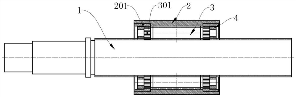
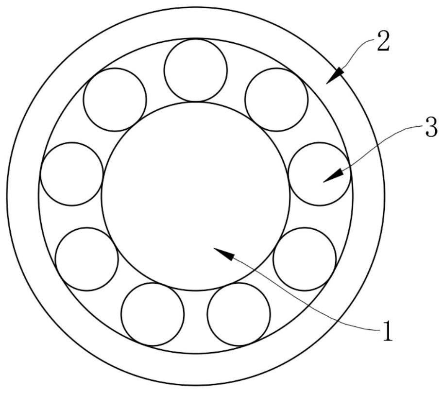
[0021] Such as figure 1 , figure 2 with image 3 As shown, this embodiment provides a planetary roller screw with deceleration function, including a screw 1, a nut 2 and a number of rollers 3 located between the outer circumference of the screw 1 and the inner circumference of the nut 2. The outer periphery is also covered with a cage 4, and the cage 4 is provided with a number of retaining holes, and the rollers 3 are inserted in the retaining holes in a one-to-one correspondence; ring 201, and an external gear 301 meshing with the internal gear 201 is provided at both ends of each roller 3, and the meshing be...


PUM


Abstract

The invention relates to a planetary roller screw with the decelerating function. The planetary roller screw with the decelerating function comprises a lead screw, a nut and a plurality of rollers located between the outer periphery of the lead screw and the inner periphery of the nut. The outer periphery of the lead screw is further sleeved with a retainer. The retainer is provided with a plurality of retaining holes. The rollers are arranged in the retaining holes in a penetrating manner and are in one-to-one correspondence to the retaining holes. Internal threads are arranged on the inner periphery of the nut. The outer periphery of each roller is provided with first external threads meshed with the internal threads. The outer periphery of the lead screw is provided with second externalthreads meshed with the first external threads. The screw directions of the internal threads and the first external threads are identical. The screw directions of the second external threads and thefirst external threads are opposite. According to the planetary roller screw with the decelerating function, the screw directions of the lead screw and the nuts are different, so that the transmissionratio of the roller screw can be conveniently designed by changing the diameter ratio of the lead screw and the rollers, the screw pitch of the lead screw and the number of threads of the lead screw,and the roller screw has the decelerating function.

Description

technical field [0001] The invention relates to the technical field of planetary roller screws, in particular to a planetary roller screw with deceleration function. Background technique [0002] The planetary roller screw was first invented by the Swedish Carl Bruno Strandgren in 1942, but it has not been widely used because of its complex structure and high machining accuracy. It was not until the 1980s that due to the advancement of processing technology, especially the popularization of CNC processing equipment and the promotion of market demand, this technology was gradually applied and developed, and it was increasingly used in various industrial fields. The characteristics of the planetary roller screw are: 1) high load capacity and long life; relative to the ball screw, the load capacity can be increased by about 3-5 times, and the life span can reach nearly 10-15 times that of the ball screw; 2) high input speed High output speed, the maximum input speed can reach ...

Claims


Application Information

Patent Timeline
Patent Type & Authority Applications(China)
IPC IPC(8): F16H25/22
CPCF16H25/2252F16H25/2266
Inventor 李桐谋
Owner 李桐谋
Why Eureka
Try Eureka