Supercharge Your Innovation With Domain-Expert AI Agents!

Sample cup conveying mechanism of water quality detection equipment and water quality detection equipment

A technology of water quality detection and transportation mechanism, which is applied in the direction of analyzing materials, instruments, etc., can solve the problems of heavy workload and low efficiency, and achieve the effect of reducing labor load

Active Publication Date: 2020-10-02
哈尔滨跃渊环保智能装备有限责任公司
View PDF9 Cites 1 Cited by
  • Summary
  • Abstract
  • Description
  • Claims
  • Application Information

AI Technical Summary

Problems solved by technology

Manual operation, heavy workload and low efficiency

Method used


Image

  • Sample cup conveying mechanism of water quality detection equipment and water quality detection equipment
  • Sample cup conveying mechanism of water quality detection equipment and water quality detection equipment
  • Sample cup conveying mechanism of water quality detection equipment and water quality detection equipment

Examples


Embodiment 1

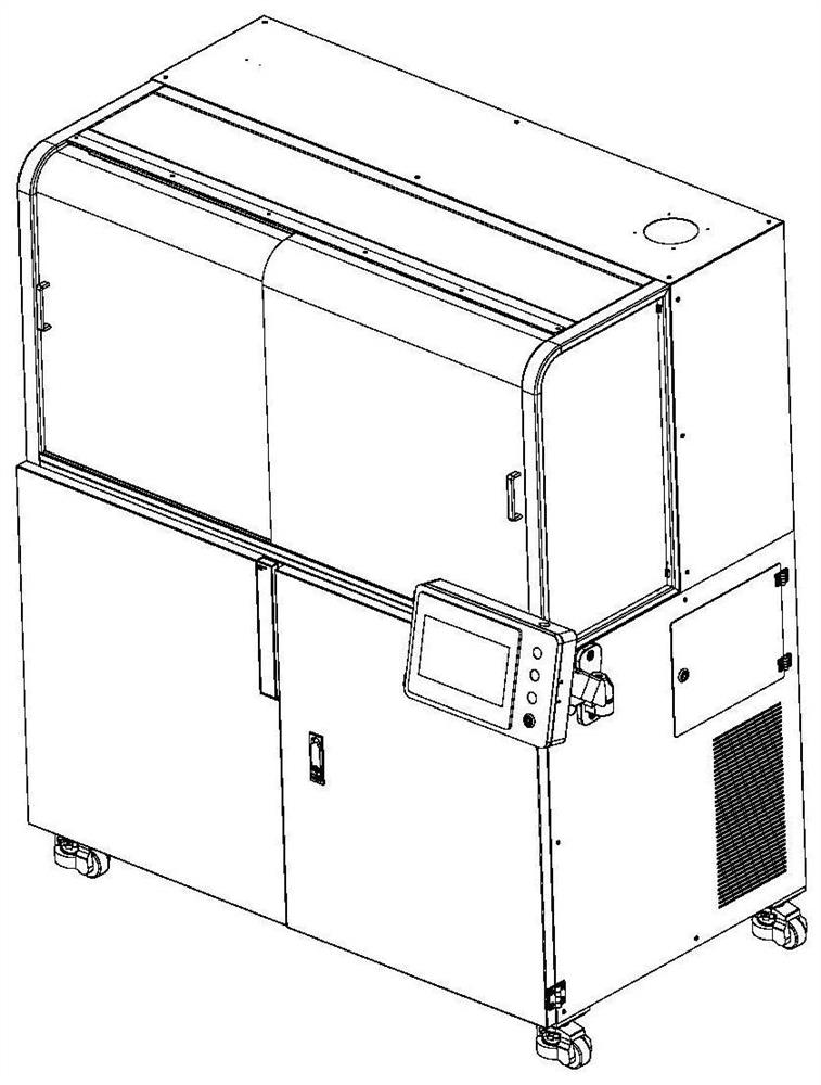
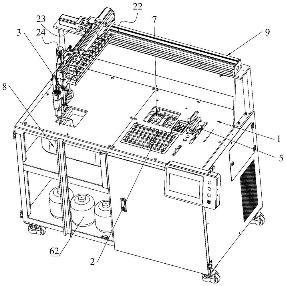
[0069] Such as Figure 1-13 Shown, a kind of water quality detection equipment, can automatically detect water quality, comprises frame 1, is installed on frame 1;

[0070] Storage rack 2, for placing test tube and cuvette 66;

[0071] Mobile grabbing mechanism 3 for grabbing items and taking samples;

[0072] The switch cover mechanism 4 is used to open or close the test tube cover 71 of the test tube;

[0073] The dosing mechanism 5 is used to add medicine to the test tube body 46;

[0074] Shaking mechanism 6, used to fully mix the sample and the medicament;

[0075] Digester 7, used to heat and digest the shaken liquid;

[0076] The detector 8 is used to detect the liquid in the contrast color dish 66 .

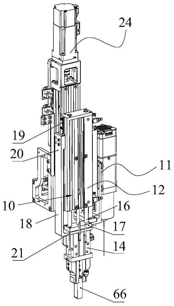
[0077] Such as figure 2 , 3 Shown in and 4, in the present embodiment, mobile grasping mechanism 3 comprises:

[0078] a mobile unit 9;

[0079] The mounting frame 11 is installed on the mobile unit 9;

[0080] The first lifting element 12 is installed on the m...

Embodiment 2

[0161] Such as Figure 17 and 18 As shown, the difference between this embodiment and Embodiment 1 is that the digestion apparatus 7 is removed in this embodiment, and a heating element 70 is added on the basis of the shaking mechanism 6 in Embodiment 1 to form a shaking heating mechanism. Such as Figure 17 and 18 As shown, the shake well heating mechanism consists of:

[0162] the first rotating element 43;

[0163] The second rotating element 44 is fixed to the rotating shaft of the first rotating element 43, and the rotating shaft axis of the second rotating element 44 is perpendicular to the rotating shaft axis of the first rotating element 43;

[0164] The test tube self-clamping sleeve 45 is fixed to the rotating shaft of the second rotating element 44 for automatically clamping the test tube body 46 , and the test tube self-clamping sleeve 45 is equipped with a heating element 70 .

[0165] Through the first rotating element 43 and the second rotating element 44 ,...

Embodiment 3

[0172] The difference between this embodiment and embodiment 1 or 2 is that test tube and switch cover mechanism 4 are different, as Figure 19 and 20 As shown, the test tube assembly of this embodiment includes a test tube body 46 and a test tube cover 71. The test tube cover 71 is socketed and fitted with the test tube body 46. The test tube cover 71 includes an inner insertion part 72 and an outer outer part 73 arranged coaxially. An annular groove 74 is formed between the outer portion 72 and the outer sleeve portion 73, and the annular groove 74 is used to be clamped on the opening end of the test tube body 46; the inner insertion portion 72 is a cylindrical structure, and the end of the inner insertion portion 72 has a first tapered shape. Guide surface 75; test tube cover 71 is a flexible material, and the inner sidewall 72 of test tube cover 71 is sealed with the inner wall of test tube body 46, and the outer wall of test tube cover 71 is sealed with the outer wall of ...


PUM


Abstract

The invention discloses a sample cup conveying mechanism of water quality detection equipment and the water quality detection equipment. The sample cup conveying mechanism comprises a cup pushing element, an input assembly and an output assembly. Each of the input assembly and the output assembly comprises a frame, two rollers which are rotationally mounted on the frame, a conveying belt which iswound on the two rolling wheels and is provided with a plurality of containing grooves in the outer surface, and a conveying belt driving motor which is used for driving one of the rollers to rotate.The cup pushing element is used for pushing a sample cup in the input assembly into a sampling position and pushing the sample cup at the sampling position into an accommodating groove of the output assembly. According to the sample cup conveying mechanism, the sample cup can be automatically conveyed and moved out, and compared with manual operation, the labor amount can be effectively reduced.

Description

technical field [0001] The invention relates to the field of water quality detection, in particular to a sample cup conveying mechanism of water quality detection equipment and water quality detection equipment. Background technique [0002] Municipal sewage plants and other places require laboratory technicians to test the sewage in and out water samples every day, such as COD, BOD, total nitrogen, total phosphorus and other indicators. The samples are generally placed in the sample cup, and each time the test is performed, the sample cup needs to be manually placed on the working position, and then the testing equipment sucks the sample through the automatic structure and performs related testing operations. After the sample cup is drawn, it needs to be manually Remove the sample cup and place in a new untested sample cup. By manual operation, the workload is large and the efficiency is low. Contents of the invention [0003] Aiming at the above problems, the present i...

Claims


Application Information

Patent Timeline
Patent Type & Authority Applications(China)
IPC IPC(8): G01N35/04G01N35/00
CPCG01N35/04G01N35/0099G01N2035/0441G01N2035/0453
Inventor 李杰
Owner 哈尔滨跃渊环保智能装备有限责任公司
Features
  • R&D
  • Intellectual Property
  • Life Sciences
  • Materials
  • Tech Scout
  • Unparalleled Data Quality
  • Higher Quality Content
  • 60% Fewer Hallucinations
Learn More