Supercharge Your Innovation With Domain-Expert AI Agents!

Large-aperture vehicle-mounted deployable composite material antenna

A composite material, large-diameter technology, applied in the field of large-diameter vehicle-mounted deployable composite material antennas, can solve the problems of deployment efficiency and reflector accuracy, low stiffness, high technical level requirements for operators, and complex deployable antenna structures. Compact structure, good lightweight effect and simple structure

Pending Publication Date: 2020-10-02
HUNAN AEROSPACE HUNAYU COMM TECH CO LTD
View PDF0 Cites 1 Cited by
  • Summary
  • Abstract
  • Description
  • Claims
  • Application Information

AI Technical Summary

Problems solved by technology

So far, vehicle-mounted deployable composite antennas generally use umbrella-shaped mesh antennas or fixed-surface antennas, which have a limited storage ratio (ratio of the expanded diameter of the reflective surface to the retracted diameter), and relatively low deployment efficiency, reflective surface accuracy, and stiffness. The technical level of the operator is high
[0006] Generally speaking, the existing deployable antennas have disadvantages such as complex structure, large mass, and low deployment efficiency, and technical innovations in high precision, large storage ratio, and lightweight are needed.

Method used


Image

  • Large-aperture vehicle-mounted deployable composite material antenna
  • Large-aperture vehicle-mounted deployable composite material antenna
  • Large-aperture vehicle-mounted deployable composite material antenna

Examples


Embodiment Construction

[0048] In order to facilitate the understanding of the present invention, the present invention will be described more fully and in detail below in conjunction with the accompanying drawings and preferred embodiments, but the protection scope of the present invention is not limited to the following specific embodiments.

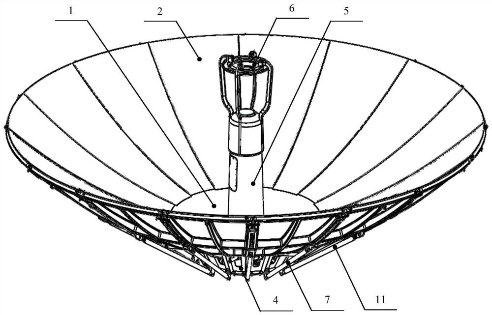
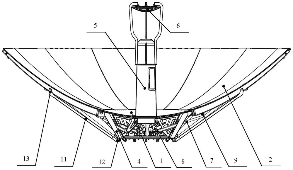
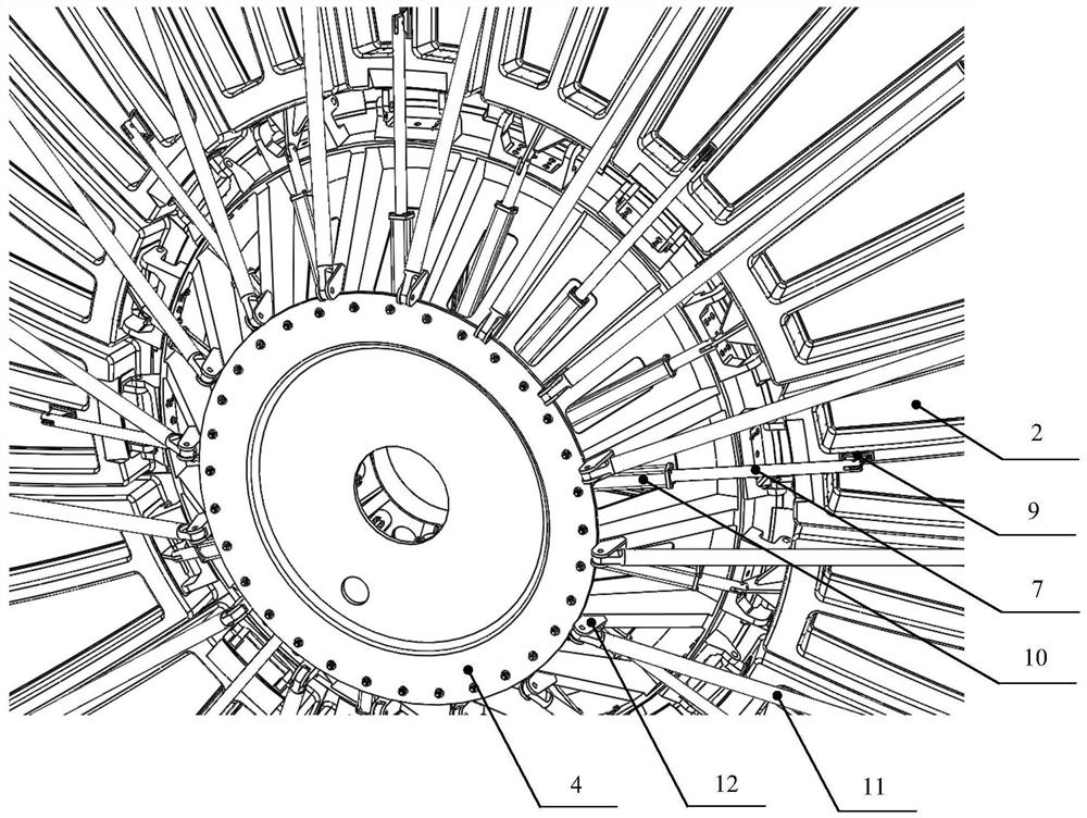
[0049] Such as Figure 1-Figure 8 As shown, the large-diameter vehicle-mounted expandable composite material antenna of this embodiment includes a circular mounting tray 4, a fixed reflective surface 1 fixedly connected to the top of the mounting tray 4 and located in the central area, and 16 expandable and fixed reflective surfaces. 1 forming the melon petal reflective surface 2 of the complete antenna main reflective surface, and 16 driving parts (preferably electric push rods 7) that drive the melon petal reflective surface 2 to expand, and the outer edge of the fixed reflective surface 1 is uniformly provided with 16 Alternate concave and convex positioni...


PUM

PropertyMeasurementUnit
Caliberaaaaaaaaaa

Abstract

The invention discloses a large-caliber vehicle-mounted deployable composite material antenna, which comprises a mounting tray, a fixed reflecting surface, a plurality of expandable melon petal reflecting surfaces and a plurality of driving pieces, wherein a plurality of positioning grooves and positioning flanges which are arranged at intervals are uniformly formed in the edge of the outer ring of the fixed reflecting surface, the back faces of the bottom ends of the melon petal reflecting surfaces can be hinged to the peripheral edge of the top of the mounting tray, when the driving pieces drives the melon petal reflecting surfaces to be unfolded, the bottom ends of the melon petal reflecting surfaces are located in the corresponding positioning grooves or located on the corresponding positioning flanges respectively, every two adjacent melon petal reflecting surfaces are supported and limited through a supporting assembly, and when the driving pieces drive the melon petal reflectingsurfaces to be folded, the melon petal reflecting surfaces positioned in the positioning grooves are folded towards the bottom of the antenna, and the melon petal reflecting surfaces positioned on the positioning flanges are folded towards the top of the antenna. According to the invention, the large-caliber vehicle-mounted deployable composite material antenna has the advantages of high precision, high rigidity, light weight, large storage ratio, automatic folding and unfolding and the like, meets the requirements of vehicle carrying and road over-limit transportation, and can be used in a ground vehicle-mounted mobile communication system and a satellite communication system.

Description

technical field [0001] The invention relates to an antenna, in particular to a large-diameter vehicle-mounted expandable composite material antenna. Background technique [0002] In modern communication systems, antennas, as devices for transmitting or receiving electromagnetic waves into space, play a decisive role in communication performance. With the increase of the amount of information, people have more and more urgent demands on the functions of antennas such as large capacity, high power, and multi-spectral bands. It is necessary to increase the aperture of the antenna as a prerequisite. [0003] As for the movable antenna, while the aperture increases, the transportation difficulty is also increased. At present, the application of vehicle-mounted integral reflector antennas with a diameter of more than 3 meters is restricted. Therefore, the development of large-diameter deployable antennas has gradually attracted attention and has become a research hotspot. [000...

Claims


Application Information

Patent Timeline
IPC IPC(8): H01Q15/16
CPCH01Q15/162
Inventor 李林才王贵林李嘉祥彭国勋刘珺王洲
Owner HUNAN AEROSPACE HUNAYU COMM TECH CO LTD
Features
  • R&D
  • Intellectual Property
  • Life Sciences
  • Materials
  • Tech Scout
  • Unparalleled Data Quality
  • Higher Quality Content
  • 60% Fewer Hallucinations
Learn More