
Attachment structure of motor rotor with low temperature winding

A technology of motor rotor and auxiliary structure, applied in the direction of magnetic circuit shape/style/structure, electromechanical devices, electrical components, etc., can solve the problems of low temperature winding performance degradation, unavoidable multiple sealing surfaces, and unfavorable long-term stable operation of the motor, etc. Achieve the effect of preventing small leaks, avoiding motor downtime for maintenance and inspections

Active Publication Date: 2020-12-01
TSINGHUA UNIV
View PDF7 Cites 0 Cited by
  • Summary
  • Abstract
  • Description
  • Claims
  • Application Information

AI Technical Summary

Problems solved by technology

Due to the existence of outgassing materials for heat insulation support inside the rotor vacuum cavity, and the inevitable multiple sealing surfaces on the outside, and the impact of various vibrations during the operation of the motor, it is difficult to ensure that the rotor vacuum cavity is running properly. The vacuum degree remains unchanged for a long time during the process
When the vacuum degree of the rotor vacuum cavity drops during the operation of the motor rotor with low-temperature winding, the cooling power consumption of the low-temperature winding on the rotor will increase, and the performance of the low-temperature winding will decrease, which is not conducive to the long-term stable operation of the motor

Method used


Image

  • Attachment structure of motor rotor with low temperature winding
  • Attachment structure of motor rotor with low temperature winding
  • Attachment structure of motor rotor with low temperature winding

Examples


Embodiment Construction

[0035] Embodiments of the present invention are described in detail below, examples of which are shown in the drawings, wherein the same or similar reference numerals designate the same or similar elements or elements having the same or similar functions throughout. The embodiments described below by referring to the figures are exemplary only for explaining the present invention and should not be construed as limiting the present invention.

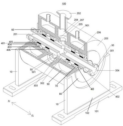
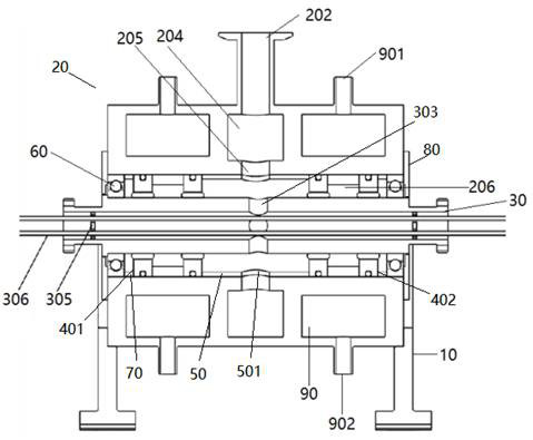
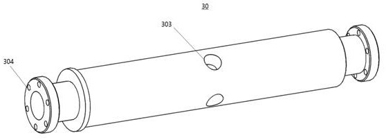
[0036] Refer below Figure 1-Figure 6 A motor rotor attachment structure 100 with low temperature windings according to an embodiment of the present invention is described. The motor rotor attachment structure 100 with low temperature windings can continuously evacuate the motor rotor vacuum cavity 200 with low temperature windings.

[0037] Such as Figure 1-Figure 6 As shown, the motor rotor accessory structure 100 with low-temperature winding according to the embodiment of the present invention includes: a support base 10 , a frame 2...


PUM


Abstract

The invention discloses a motor rotor accessory structure with a low-temperature winding. The motor rotor accessory structure comprises: a supporting seat; a rack arranged on the supporting seat and defining a mounting space; a hollow rotating shaft arranged in the mounting space and capable of rotating relative to the rack; a sealing assembly arranged between the hollow rotating shaft and the rack; and a gas sucking opening formed in the rack and communicated with the hollow rotating shaft cavity of the hollow rotating shaft. According to the invention, by matching the rack, the hollow rotating shaft and the gas sucking opening, two ends of the hollow rotating shaft are respectively communicated with the motor rotor vacuum cavity, and the motor rotor in rotary work can continuously discharge gas through the gas sucking opening, so that the situation that the air pressure of the vacuum cavity of the motor rotor rises due to tiny leakage or partial material deflation in the vacuum cavity of the motor rotor can be prevented, and shutdown maintenance and inspection of the motor due to leakage of the vacuum cavity of the motor rotor are avoided.

Description

technical field [0001] The invention relates to the field of motors with low-temperature windings, in particular to a motor rotor accessory structure with low-temperature windings. Background technique [0002] For traditional rotating electrical machines, in order to achieve higher air-gap magnetic density of the motor rotor, more windings need to be installed on the rotor and a larger excitation current should be passed in. Due to the limitation of the material properties of the traditional conductor itself, when the motor power is too At high temperature, the manufacturing cost and operating cost of the excitation winding of the motor rotor working at room temperature will rise sharply. In order to develop large-scale motors with high power density, the development of motor rotor technology with low-temperature windings has great application value. The current development has Motor rotors with cryogenic windings include superconducting motor rotors, hydrogen-cooled copper...

Claims


Application Information

Patent Timeline
Patent Type & Authority Patents(China)
IPC IPC(8): H02K5/04H02K5/20H02K5/124H02K1/32H02K5/16
CPCH02K1/32H02K5/04H02K5/124H02K5/161H02K5/20
Inventor 吴其红瞿体明宋彭杨置荣冯峰
Owner TSINGHUA UNIV
Learn More