Clamping device, tearing device, raw material tearing equipment and processing method

A clamping device and raw material technology, applied in metal processing, plant protein processing, food forming, etc., can solve the problems of destroying fiber structure, reducing the taste of vegetable protein meat, etc., and achieve simple operation, easy installation, and neat tearing Effect

Pending Publication Date: 2020-10-09
JIANGNAN UNIV
View PDF0 Cites 1 Cited by
  • Summary
  • Abstract
  • Description
  • Claims
  • Application Information

AI Technical Summary

Problems solved by technology

Most of the machines currently on the market for processing vegetable protein raw materials mostly use blades to cut raw materials into slices or mince meat. These methods destroy the fiber structure of raw materials and greatly reduce the taste of vegetable protein meat.

Method used


Image

  • Clamping device, tearing device, raw material tearing equipment and processing method
  • Clamping device, tearing device, raw material tearing equipment and processing method
  • Clamping device, tearing device, raw material tearing equipment and processing method

Examples


Embodiment 1

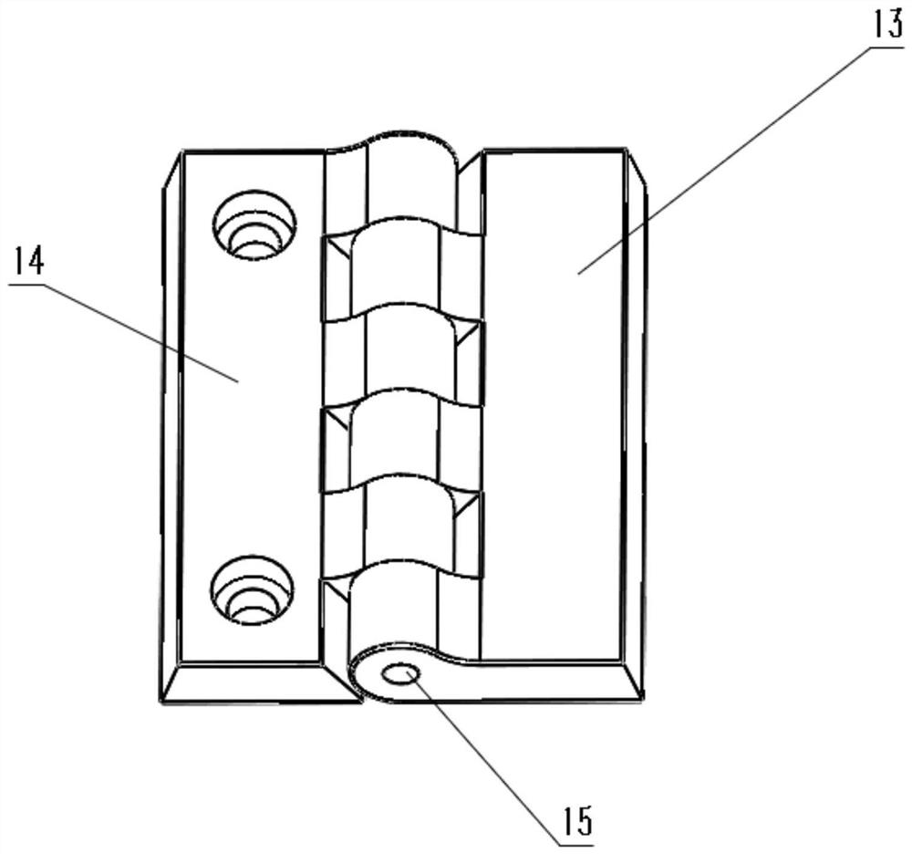
[0031] A clamp, especially suitable for clamping sheet materials, each clamp 29 includes two clamping plates, one end of the two clamping plates is close to each other, the end distance between these ends is small, and the end distance between the other ends is relatively large , an electromagnet 30 is arranged in the middle of each splint, that is, a clip 29 has two electromagnets 30, and the electromagnet 30 is located on the opposite side of the splint. When several splints are arranged in a row and the surface of the splint When oppositely arranged, the electromagnets 30 of adjacent two groups of splints are close to each other.

[0032] When the electromagnet is energized, the two splints of a clip 29 are affected by the magnetic force and approach each other to clamp the raw material.

Embodiment 2

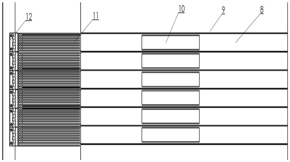
[0034] A clip row moving device uses the clips 29 in Embodiment 1. Several clips 29 are installed on a strip-shaped fixed block 28 and arranged in a linear array. These clips 29 are all located on the same side of the fixed block 28 .

[0035] The two ends of the clamp 29 are respectively: one end connected to the fixed block 28, one end for clamping the food raw material, the initial state of the one end for clamping the food raw material is an open state, and the initial state of the other end is a closed state, And embedded in the fixed block 28 .

[0036] The side of the fixed block 28 facing away from the clip 29 is provided with a clip row slider 27, and the clip row slider 27 is located in the middle of the elongated fixed block 28; the side of the fixed block 28 away from the clip 29 is also provided with a clip row connecting block 25. The clip bar connecting block 25 is provided with a clip bar sliding groove 26 for accommodating the clip bar sliding block 27 to reci...

Embodiment 3

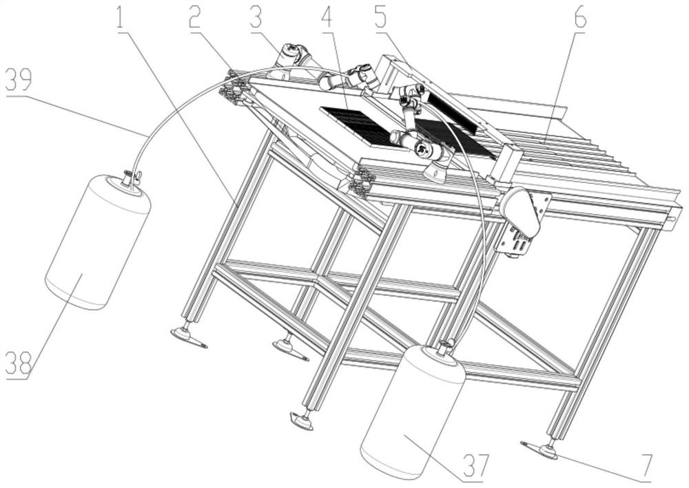
[0039] A material tearing device is arranged on a frame 1, the top surface of the frame 1 is a rectangular table top located in a horizontal plane, and the material tearing device 5 is located near the middle of the top surface of the frame 1. The clip 29 in the first embodiment, and the clip moving device 16 in the second embodiment are used.

[0040] The material tearing device 5 includes a sliding structure, and the sliding structure is used for reciprocating sliding on the frame 1. Under the premise that the clip 29 holds the material, the clip 29 is driven to move, and the material is torn into small strands from large pieces.

[0041] The sliding structure includes a front horizontal chute 21 and a rear horizontal chute 24 located at one edge of the frame 1 , and the front horizontal chute 21 and the rear horizontal chute 24 are parallel to each other. The front section horizontal chute 21 is set as a flat slot, and the flat slot is vertically arranged, and the narrower si...


PUM


Abstract

The invention discloses a clamp, a clamp row moving device, a tearing device, tearing equipment and a method. Processing of meat is realized through cooperative work of a module lifting device, an automatic feeding manipulator, a raw shredded meat molding module, a raw meat tearing device and a vegetable protein meat raw material conveying device, and a vegetable protein meat raw material can be cut without damaging the fiber structure of drawing proteins. Meanwhile, raw shredded meat is mixed with auxiliary materials to be further processed into vegetable protein meat of specific shapes.

Description

technical field [0001] The invention belongs to the application field of food equipment, and relates to a clamping device, a material tearing device, raw material tearing equipment and a processing method. Background technique [0002] According to the data released by the United Nations Department of Economic and Social Affairs, the world population will reach 9.7 billion by 2050, and the global meat product market demand gap will reach 38 million tons; while meat and dairy products provide 18% of calories and 37% of energy for humans. Protein, however, occupies 83% of human farmland and emits 60% of agricultural greenhouse gases, causing problems such as overuse of land and water, acidification of water bodies, and negative nutrition. In order to alleviate the pressure of resource consumption and environmental protection, many food companies around the world have begun to pay attention to the vegetable protein meat market. [0003] Thanks to social media, the globalizatio...

Claims


Application Information

Patent Timeline
IPC IPC(8): B26F3/02A23J3/14A23L33/185A23P30/00
CPCB26F3/02A23J3/14A23L33/185A23P30/00
Inventor 周景文宁萌陈坚陈洁王召君
Owner JIANGNAN UNIV
Why Eureka
Try Eureka