Device of separating upper covers of dies continuously for automatic initiating explosive device assembling production line

An automatic assembly and separation device technology, applied in the direction of transportation, packaging, conveyors, etc., can solve the problems of low degree of automation, aging equipment, increased production costs, etc., and achieve the effect of simple structure and high efficiency

Inactive Publication Date: 2020-10-09
CHANGCHUN EQUIP TECH RES INST
View PDF6 Cites 0 Cited by
  • Summary
  • Abstract
  • Description
  • Claims
  • Application Information

AI Technical Summary

Problems solved by technology

At this stage, the status quo of my country's pyrotechnic product production line is not optimistic. There are widespread phenomena such as aging equipment, low automation, and crowd tactics. Especially in the process of separating the mold cover, many manufacturers are still using manual operations or upgrading to Manipulator operation
The production efficiency of manual operation is extremely low, and a large number of workers are required to participate, which increases the production cost, and due to the endless repetition of single work, the workers need to bear great labor intensity; the use of manipulators to grab the upper cover of the mold requires an additional mold positioning mechanism , the pneumatic-driven manipulator has inaccurate control and is difficult to adjust the speed; the servo motor-driven manipulator has flexible and reliable movements and accurate positioning, but the cost of explosion-proof servo manipulators and maintenance is high, requiring high technical level of operators, resulting in some Enterprises can't bear it

Method used


Image

  • Device of separating upper covers of dies continuously for automatic initiating explosive device assembling production line
  • Device of separating upper covers of dies continuously for automatic initiating explosive device assembling production line
  • Device of separating upper covers of dies continuously for automatic initiating explosive device assembling production line

Examples


Embodiment Construction

[0012] The present invention will be described in further detail below in conjunction with the accompanying drawings and specific embodiments.

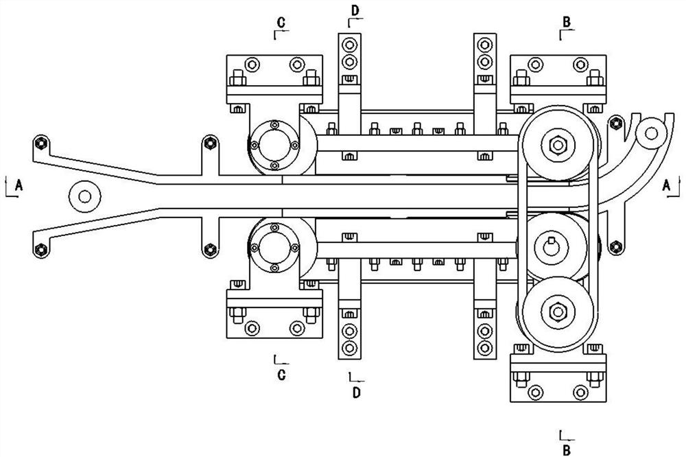
[0013] The mold cover separating device is composed of four parts: guide rail device, front conveying device, belt adjusting device and rear conveying device.

[0014] Rail device:

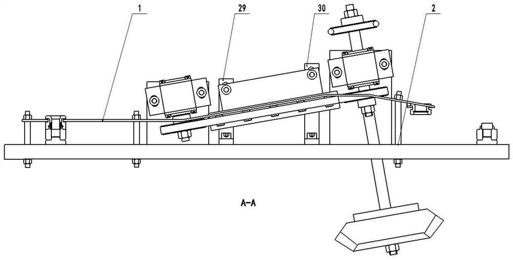
[0015] see figure 2 , the guide rail (1) on the guide rail device is fixed on the conveying platform through two guide rail pillars (2) and six screws, and the six screw rods are adjusted to ensure that the guide rail is parallel to the conveying platform, and the two guide rail pillars are adjusted to make the separated mold The upper cover smoothly enters the return conveying line, and the inclined part of the guide rail maintains an inclination angle of 10 degrees with the platform, so that the mold upper cover and the mold can be conveyed layer by layer.

[0016] Front conveyor:

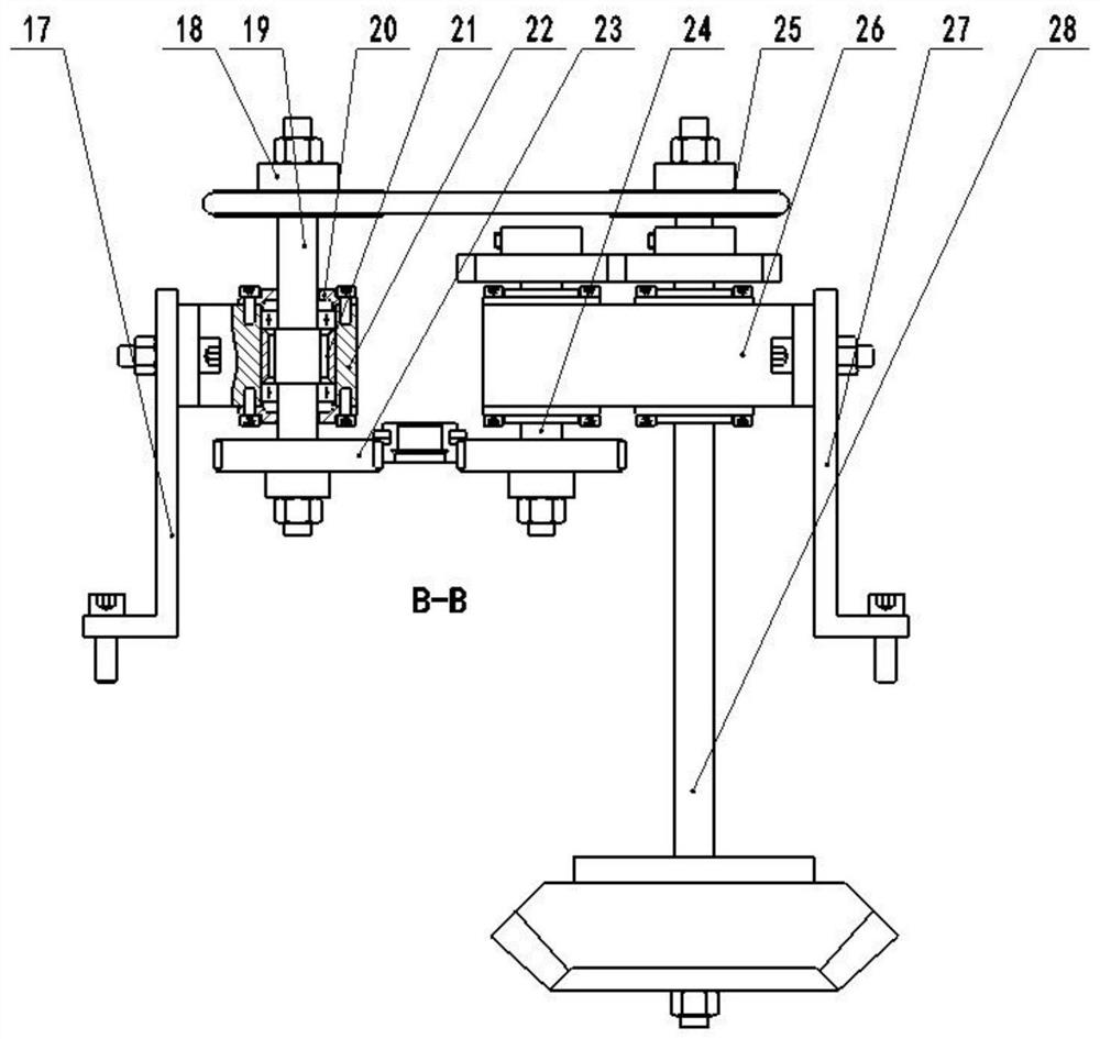
[0017] see image 3 and Figure 4 , the front transmission device...


PUM


Abstract

The invention relates to a device of separating upper covers of dies. The device is composed of four parts: a guide rail device, a front conveying device, a belt adjusting device and a back conveyingdevice. The guide rail device is used for separating and transferring the upper covers of the dies; the front conveying device is used for driving the upper covers of the dies to enter the guide raildevice smoothly; the belt adjusting device is used for adjusting a tensile force of a belt and enabling ten bearings to be in contact with the belt tightly through a spring to ensure that the upper covers of the dies are obliquely and continuously conveyed along the guide rail device; and the back conveying device is used for driving the upper covers and the dies to move forward on a guide rail and conveying the separated upper covers of the dies back to a conveyor line. The dies with to-be-separated upper covers of the dies move at a speed of 20 m/min on the conveyor belt, rectangular slot bodies are formed in the outer diameters of the upper covers of the dies, and the upper covers enter the rectangular slot bodies by a shifting fork in the oblique guide rail device. The dies are conveyed on the conveyor belt at an original speed, and the upper covers of the dies are driven by the shifting fork to move upward along the inclined guide rail, so that the upper covers of the dies are separated from the dies to achieve a demand of separating the upper covers of the dies automatically. The separated upper covers of the dies are conveyed back to original stations through the conveyor belt and the rest of dies are further conveyed to follow-up stations to be assembled.

Description

technical field [0001] The invention relates to a continuous separation device for a mold upper cover used in an automatic assembly line of pyrotechnic products. Background technique [0002] The mold upper cover continuous separation device (hereinafter referred to as the mold cover separation device) is one of the key equipments in the automatic assembly line of pyrotechnic products, and is one of the bottleneck stations currently restricting the output of pyrotechnic products. At this stage, the status quo of my country's pyrotechnics production line is not optimistic. There are widespread phenomena such as aging equipment, low automation, and crowd tactics. Especially in the process of separating the mold cover, many manufacturers are still using manual operations or upgrading to Manipulator operation. The production efficiency of manual operation is extremely low, and a large number of workers are required to participate, which increases the production cost, and due to ...

Claims


Application Information

Patent Timeline
Patent Type & Authority Applications(China)
IPC IPC(8): B65G23/44B65G21/20
CPCB65G21/2063B65G23/44
Inventor 李京张欲立杨浩张宏光郭瑞雪朱贺母佳庆李健白孙阳洪瑞贺飞贾云鹏高君
Owner CHANGCHUN EQUIP TECH RES INST
Why Eureka
Try Eureka