Building block type cylindrical condenser

A cylindrical condenser technology, applied in steam/steam condensers, lighting and heating equipment, etc., can solve the problems of low sealing performance and pressure bearing capacity, unsuitable for small power stations, poor structural versatility, etc., to achieve Good sealing performance, saving design and manufacturing cycle, small floor space

Pending Publication Date: 2020-10-09
HARBIN TURBINE AUX EQUIP ENG
View PDF0 Cites 2 Cited by
  • Summary
  • Abstract
  • Description
  • Claims
  • Application Information

AI Technical Summary

Problems solved by technology

[0003] Purpose of the invention: This invention solves the problems that other types of condensers occupy a large space, are not suitable for small power plants, and have low sealing performance and pressure bearing capacity, and poor structural versatility. The invention proposes a building block type cylindrical condenser device

Method used


Image

  • Building block type cylindrical condenser
  • Building block type cylindrical condenser
  • Building block type cylindrical condenser

Examples


specific Embodiment approach 1

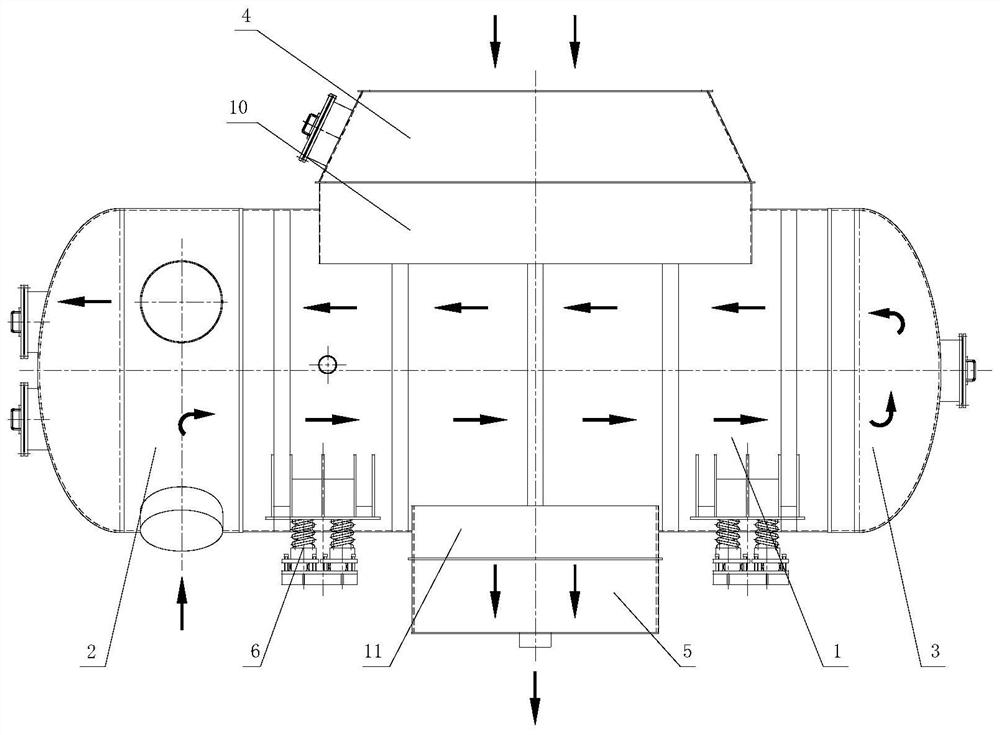
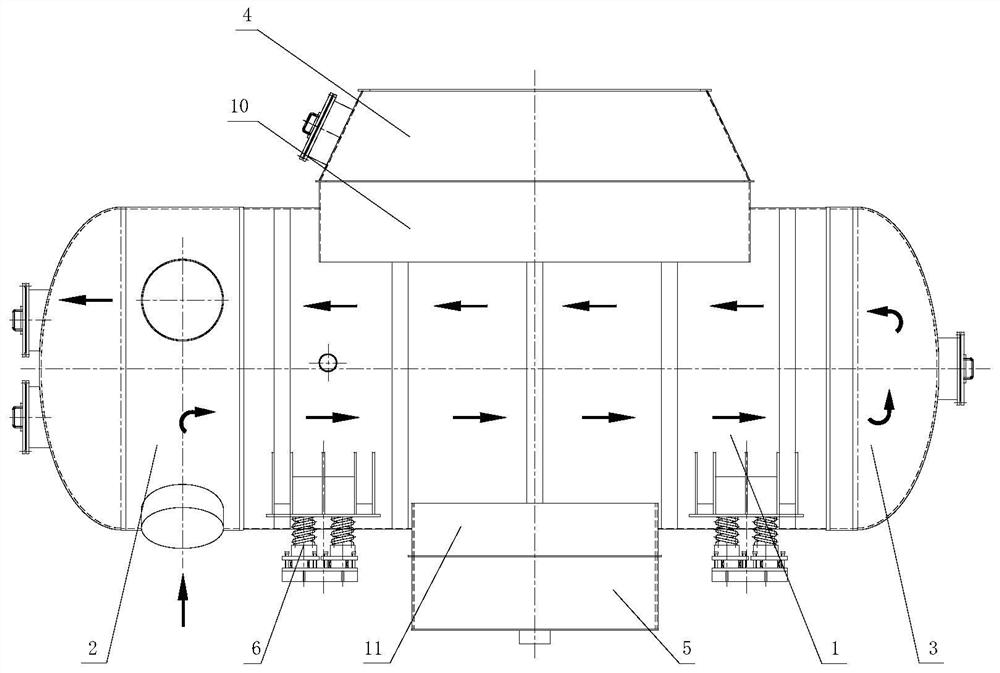
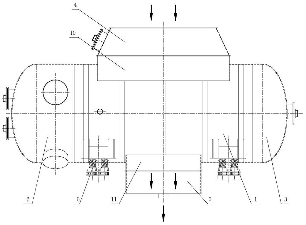
[0026] Specific embodiment 1: It includes a shell 1, an inlet and outlet water chamber 2, a return water chamber 3, an exhaust throat 4, a hot well 5 and a plurality of shock-absorbing support seats 6;

[0027] The inlet and outlet water chamber 2 is arranged at one end inside the shell 1, the return water chamber 3 is arranged at the other end inside the shell 1, the exhaust throat 4 is arranged at the upper part of the shell 1, and the hot well 5 is arranged at the shell In the lower part of the body 1 , a plurality of shock-absorbing support seats 6 are arranged on the bottom of the housing 1 .

[0028] The shell 1 is arranged with a tube bundle composed of a tube plate, heat exchange tubes and heat exchange tube support plate, the heat exchange tube support plate is fixed inside the shell 1, and the heat exchange tubes are connected and fixed through the tube plate. The support plate is evenly arranged inside to avoid the vibration of the tube bundle.

[0029] In this emb...

specific Embodiment approach 2

[0032] Embodiment 2: The casing 1 is cylindrical.

[0033] Other implementation manners are the same as the specific implementation manner 1.

specific Embodiment approach 3

[0034] Specific implementation mode three: both the inlet and outlet water chambers 2 and the return water chamber 3 adopt a head structure.

[0035] In this embodiment, both the inlet and outlet water chambers 2 and the return water chamber 3 adopt a head structure, and communicate with the inner cavity of the heat exchange tube at the same time.

[0036] Other implementation manners are the same as the specific implementation manner 1.


PUM


Abstract

The invention relates to the field of condensers, in particular to a building block type cylindrical condenser. The building block type cylindrical condenser aims to solve the problems that condensersof other types are large in occupied space, not high in sealing performance and pressure bearing capacity and poor in structural universality and comprises a shell, a hot well, a hot well transitionsection, a steam exhaust throat, a throat cylindrical transition section, an inlet and outlet water chamber, a turn-back water chamber and the like, a tube bundle composed of a tube plate, a heat exchange tube and a plurality of heat exchange tube supporting plates is mainly arranged in the shell, the inlet and outlet water chamber and the turn-back water chamber are respectively fixed at two endsof the cylinder and are communicated with an inner cavity of the heat exchange tube; the hot well and the steam exhaust throat part are installed at the bottom and the top of the integrated cylinderand communicated with the cylinder, and the hot well and the steam exhaust throat part can be universally used for condensers of the same grade by adjusting the specification of the integrated cylinder. The building block type cylindrical condenser is mainly used for small-sized power stations of 100MW grade and below, and the advantages of the small-sized power stations with high-back-pressure operation conditions are more prominent.

Description

technical field [0001] The invention relates to the field of condensers, in particular to a building block cylindrical condenser. Background technique [0002] At present, the domestic market for small power stations of 100MW and below is becoming more and more extensive. Faced with the boundary conditions of small circulating water volume, small heat exchange area and high back pressure operation, the commonly used square condenser has no advantages in terms of floor space, sealing performance or pressure bearing capacity. In order to effectively reduce the footprint of the condenser, pursue a more compact and economical plant layout, and improve the versatility of the condenser structure, a new condenser is needed to replace the square or semicircular condenser structure. Contents of the invention [0003] Purpose of the invention: This invention solves the problems that other types of condensers take up a lot of space, are not suitable for small power plants, and have ...

Claims


Application Information

Patent Timeline
Patent Type & Authority Applications(China)
IPC IPC(8): F28B1/02F28B9/00
CPCF28B1/02F28B9/00
Inventor 卢日时张俊芬王琳王丽娜刘杰程方张健许宝军
Owner HARBIN TURBINE AUX EQUIP ENG
Why Eureka
Try Eureka