Communication device and communication system

A technology of communication equipment and field equipment, applied in transmission systems, digital transmission systems, data exchange through path configuration, etc., can solve the problems of long construction period, interruption of communication interference, poor stability, etc.

Pending Publication Date: 2020-10-09
BEIJING GUODIAN ZHISHEN CONTROL TONGDY
View PDF1 Cites 2 Cited by
  • Summary
  • Abstract
  • Description
  • Claims
  • Application Information

AI Technical Summary

Problems solved by technology

[0003] The above-mentioned monitoring system has the following disadvantages: 1. Long construction period: Since the entire monitoring system is composed of multiple modules such as acquisition and protocol conversion, and because the module manufacturers and communication protocols may be different, it takes a lot of manpower and time to configure, Configuration and debugging, etc., make the system construction cycle long; 2. Long delay: Since the entire monitoring cycle needs to be completed by the acquisition module, protocol conversion module, switch and other modules, the communication between modules will have a long delay, causing the system Poor safety hazard; 3. Poor stability: The structure of the above-mentioned monitoring system has a large loop; once one of the components of the input acquisition module, protocol conversion module, protocol conversion module, digital output module, and switch works abnormally, or the above-mentioned components Interference and interruption of communication between them may lead to failure of monitoring and control functions, affect system work, poor stability and reliability, and easily cause hidden dangers in production safety.
In addition, the above-mentioned monitoring system requires many hardware components and a large number of cables for interconnection, and the cost is relatively high
[0004] In summary, due to the complex composition and communication processing process of the monitoring system in the related art, there are problems such as long construction period, long delay, poor stability, and high cost.

Method used


Image

  • Communication device and communication system
  • Communication device and communication system
  • Communication device and communication system

Examples


Embodiment Construction

[0052] In order to make the purpose, technical solution and advantages of the present invention more clear, the embodiments of the present invention will be described in detail below in conjunction with the accompanying drawings. It should be noted that, in the case of no conflict, the embodiments in the present application and the features in the embodiments can be combined arbitrarily with each other.

[0053] The steps shown in the flowcharts of the figures may be performed in a computer system, such as a set of computer-executable instructions. Also, although a logical order is shown in the flowcharts, in some cases the steps shown or described may be performed in an order different from that shown or described herein.

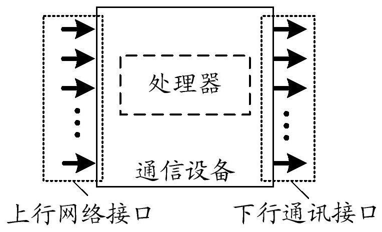
[0054] figure 2 It is a structural block diagram of a communication device according to an embodiment of the present invention, such as figure 2 shown, including:

[0055] One or more uplink network interfaces used to connect with field devices accord...


PUM


Abstract

The invention relates to a communication device and a communication system. The communication device comprises one or more uplink network interfaces for connecting to a field device according to a preset first mapping relationship and for transmitting monitoring data of a connected field device to a processor, one or more than one uplink network interface except the network interface respectivelyand independently provided with a corresponding isolation circuit and used for carrying out line isolation of an uplink network, one or more downlink communication interfaces used for being connectedwith the field device according to a preset second mapping relation and for transmitting the first control instruction issued by the processor to the connected field device and the one or more downlink communication interfaces except the internet access respectively and independently provided with a corresponding isolation circuit and used for carrying out line isolation of downlink communication.According to the embodiment of the invention, the data processing line of the monitoring system is simplified, the communication anti-interference performance is improved, and the data transmission processing time is shortened.

Description

technical field [0001] This article involves but is not limited to communication technology, especially a communication device and a communication system. Background technique [0002] In industrial control industries such as substations and power plants, there are common problems such as inconsistency in field device communication protocols, inconsistent data interfaces, easy loss of power-off data, and prolonged input and output of monitoring status digital quantities; figure 1 is a structural block diagram of a substation monitoring system in related technologies, such as figure 1 As shown, it includes: data uplink channel and data downlink channel; among them, the data uplink channel includes: after collecting the data of the field equipment through the input acquisition module, it is converted into serial port, controller area network (CAN), program bus network (Profibus), etc. The communication signal of the protocol is converted into an Ethernet signal through the p...

Claims


Application Information

Patent Timeline
Patent Type & Authority Applications(China)
IPC IPC(8): H04L12/40H04B3/04
CPCH04B3/04H04L12/40006H04L2012/40215
Inventor 徐卓彦麻贵峰王军马文婷
Owner BEIJING GUODIAN ZHISHEN CONTROL TONGDY
Why Eureka
Try Eureka