
Magnetism driving epiphysis traction and pressurization device

A pressurization device and magnetic drive technology, applied in the field of medical devices, can solve problems such as limited joint movement, low patient comfort, and patients' inability to walk with weight, and achieve the effect of improving healing and extending bone length

Pending Publication Date: 2020-10-13
姬涛
View PDF0 Cites 3 Cited by
  • Summary
  • Abstract
  • Description
  • Claims
  • Application Information

AI Technical Summary

Problems solved by technology

However, pressurizing the fracture end is currently unable to achieve the function of the intramedullary nail, mainly because the current intramedullary nail cannot be extended or shortened.
[0005] It can be seen that the fixation pins of the traditional external fixator need to pass through soft tissue structures such as muscles. These fixed metal pins often affect muscle contraction and lead to limited joint mobility. The comfort is low. In addition to the limited function of weight-bearing walking, the external fixator will affect the patient's dressing due to its large size during the treatment process.

Method used


Image

  • Magnetism driving epiphysis traction and pressurization device
  • Magnetism driving epiphysis traction and pressurization device
  • Magnetism driving epiphysis traction and pressurization device

Examples


Embodiment Construction

[0019] Preferred embodiments of the present invention will be described in detail below with reference to the accompanying drawings, so as to better understand the purpose, features and advantages of the present invention. It should be understood that the embodiments shown in the drawings are not intended to limit the scope of the present invention, but only to illustrate the essence of the technical solutions of the present invention.

[0020] In the description of the present invention, it should be understood that the orientation or positional relationship indicated by the terms "proximal", "distal", "upper", "lower", "inner", "outer" etc. The orientation or positional relationship is only for the convenience of describing the present invention and simplifying the description, but does not indicate or imply that the device or element referred to must have a specific orientation, be constructed and operated in a specific orientation, and therefore cannot be construed as limit...


PUM


Abstract

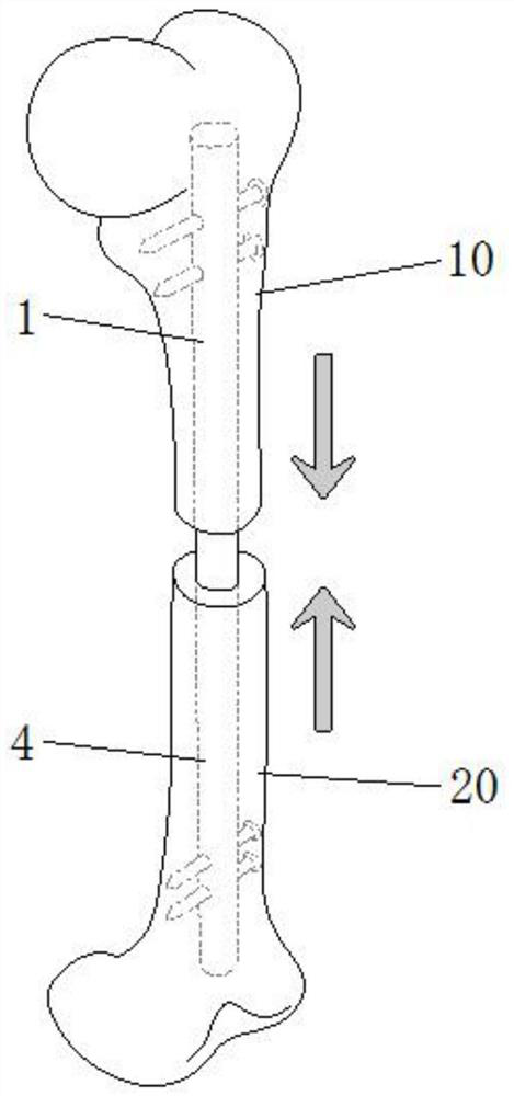
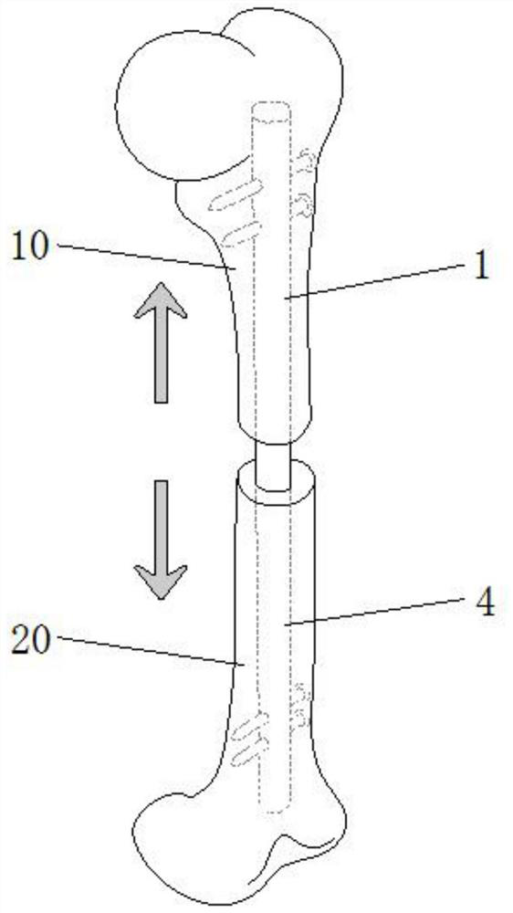
The invention relates to a magnetism driving epiphysis traction and pressurization device. The magnetism driving epiphysis traction and pressurization device comprises a near end fixing sleeve, a permanent magnet, a linear screw rod, and a far end moving sleeve, wherein the near end of the near end fixing sleeve is used for being fixed in the medullary cavity of the near end bone, and the far endof the near end fixing sleeve is used for forming an opening end; the permanent magnet is rotatably arranged in the near end fixing sleeve, and can rotate forwards or backwards around the axis of thenear end fixing sleeve; the linear screw rod is rotatably supported in the near end fixing sleeve along the axial direction of the near end fixing sleeve; the near end of the linear screw rod is connected with the permanent magnet and can synchronously rotate along with the permanent magnet; the near end of the far end moving sleeve is arranged in the near end fixing sleeve through the opening endof the near end fixing sleeve in a sliding manner; internal threads which cooperate with external threads of the linear screw rod are formed in the near end of the far end moving sleeve; the far endmoving sleeve is in threaded rotating cooperation to the linear screw rod; and the far end of the far end moving sleeve is used for being fixed in a medullary cavity of the far end bone. Through the adoption of the magnetism driving epiphysis traction and pressurization device disclosed by the invention, periosteum at an osteotomy location can be subjected to traction in a noninvasive and uniform-speed manner to induce ossification of the periosteum, so that the length of skeletal is extended, and continuous pressurizing effect can also be provided for the fracture end through abbreviation topromote healing of the fracture end.

Description

technical field [0001] The invention relates to a medical device, in particular to a magnetically driven bone end retraction / compression device capable of realizing fracture end retraction or compression in the long bone medullary cavity. Background technique [0002] Orthopedic problems such as clinical developmental limb unequal length, loss of limb length due to severe trauma, and nonunion of fracture ends usually require surgical treatment. The healing of fracture ends after common long bone fractures of extremities depends on factors such as local blood supply and stability. At present, the commonly used methods in clinical practice are internal fixation (plate, intramedullary nail) and external fixation (external fixation frame, plaster). Different methods can The stability provided is different, with their own advantages and disadvantages: [0003] (1) Limb shortening caused by various reasons. Due to severe trauma, infection, tumor, congenital development and other ...

Claims


Application Information

Patent Timeline
Patent Type & Authority Applications(China)
IPC IPC(8): A61B17/56A61B17/72
CPCA61B17/56A61B17/7216A61B17/7225A61B2017/564
Inventor 姬涛
Owner 姬涛
Learn More