Automatic assembling production technology for chargers

A technology of automatic assembly and production process, applied in metal processing, manufacturing tools, metal processing equipment, etc., can solve the problems of time-consuming, labor-intensive, labor-intensive, and low production efficiency

Inactive Publication Date: 2020-10-13
长兴梦晨节能设备有限公司
View PDF0 Cites 1 Cited by
  • Summary
  • Abstract
  • Description
  • Claims
  • Application Information

AI Technical Summary

Problems solved by technology

[0005] The purpose of the present invention is to address the deficiencies of the prior art, by setting the finished chargers to work in groups, automatically arrange the assembled chargers into groups, and use the grouped chargers to adjust the orientation to work, which will have One side of the plug is set up and batch output of finished chargers is realized in batches, thus solving the technical problems that the finished chargers need to be packed one by one manually, which is time-consuming and laborious, and the production efficiency is low.

Method used


Image

  • Automatic assembling production technology for chargers
  • Automatic assembling production technology for chargers
  • Automatic assembling production technology for chargers

Examples


Embodiment 1

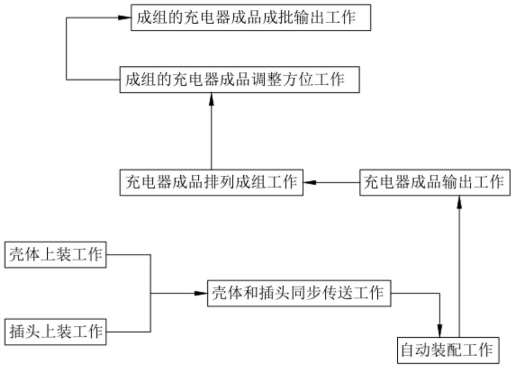
[0095] Such as figure 1 As shown, a charger automatic assembly production process, including:

[0096] Step 1, the work of top-mounting the shell, manually place the shell 20 on the receiving plate b22; Step 2, the work of top-mounting the plug, manually place the plug 10 on the receiving plate a12;

[0097] Step 3, the housing and the plug are synchronously transferred, the linear cylinder 81 of the drive mechanism 8 is activated, and the material shifting member 83 pushes the corresponding housing 20 and plug 10 to the assembly station;

[0098] Step 4, automatic assembly work, start the rotating motor 342 of the lifting assembly 34, the slide plate 344 moves downward, the suction cup a313 absorbs the housing 20, and at the same time, the flat plate 41 retreats synchronously under the drive of the first transmission member 6, and the suction cup a313 drives The shells 20 move downward together, and then the plug 10 moves into the suction cup b323 at the same time, and the p...

Embodiment 2

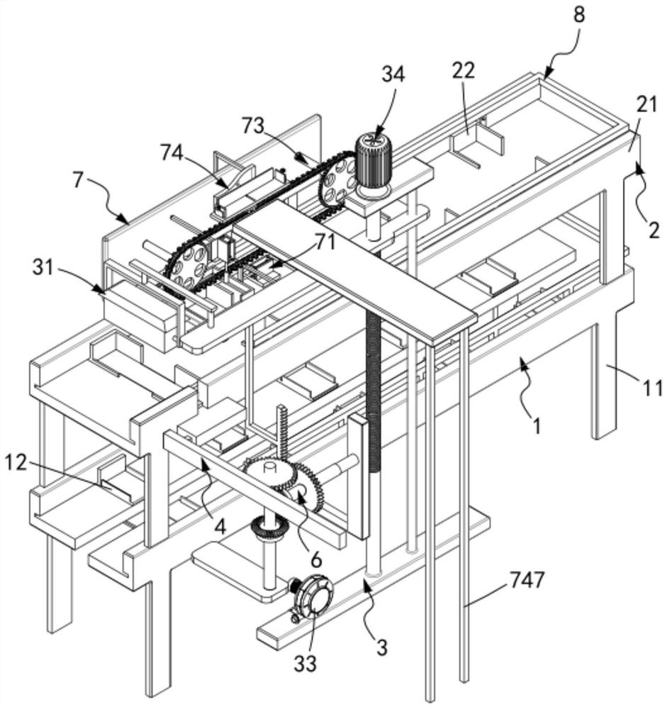
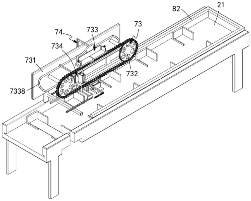
[0114] Such as figure 2 with image 3 As shown, a charger post-processing device, including:

[0115] A plug transmission mechanism 1, the plug transmission mechanism 1 includes a transmission track a11 and several sets of receiving plates a12 that are equidistantly matched and slidably arranged on the transmission track a11, and the receiving plates a12 are set to match the shape of the plug 10;

[0116] The housing transmission mechanism 2, the housing transmission mechanism 2 is arranged above the plug transmission mechanism 1, and includes a transmission track b21 and several groups of receiving plates b22 that are matched and slidably arranged on the transmission track b21 at equal intervals, the The receiving plate b22 is arranged to match the shape of the housing 20;

[0117] An automatic assembly mechanism 3, the automatic assembly mechanism 3 is located at the assembly station, and the automatic assembly mechanism 3 includes a first adsorption assembly 31 located b...

Embodiment 3

[0163] Such as Figure 22 , Figure 21 As shown, the parts that are the same as or corresponding to those in the second embodiment are marked with the corresponding reference numerals in the second embodiment. For the sake of simplicity, only the differences from the second embodiment will be described below. The difference between this embodiment three and embodiment two is:

[0164] further, such as Figure 22 , Figure 21 As shown, the flat pushing assembly 4 includes:

[0165] A flat plate 41, the flat plate 41 is matched and engaged in the transmission track b21;

[0166] A connecting frame 42, the connecting frame 42 is fixedly connected with the moving end of the flat plate 41; and

[0167] The limiting track 43 is provided with a telescopic unit b44 inside the limiting track 43 , and the telescopic unit b44 is fixedly connected with the connecting frame 42 .

[0168] In this embodiment, by setting the horizontal pushing assembly 4 to cooperate with the first tran...


PUM


Abstract

The invention relates to an automatic assembling production technology for chargers. The automatic assembling production technology for the chargers comprises the first step of shell loading work; thesecond step of plug loading work; the third step of shell and plug synchronous conveying work; the fourth step of automatic assembling work; the fifth step of charger finished product output work; the sixth step of charger finished product group arranging work; the seventh step of grouped charger finished product orientation adjusting work, wherein after charger finished products are arranged into groups, a clamping piece moves downwards under driving of a pressing piece and clamps the grouped charger finished products, and after clamping is finished, the grouped charger finished products areconveyed under driving of a chain wheel and chain unit with the sides, with plugs, of the grouped charger finished products facing upwards; and the eighth step of grouped charger finished product batched output work. The automatic assembling production technology for the chargers solves the technical problems that workers need to load charger finished products into cartons one by one, time and effort are consumed, and the production efficiency is low.

Description

technical field [0001] The invention relates to the technical field of chargers, in particular to an automatic assembly production process for chargers. Background technique [0002] The charger is a device for charging the energy storage module. In today's environment where electronic products are widely used, the charger is widely used. During the production process, when the shell is assembled, the traditional method is manual Therefore, it is easy to cause wear and tear on the charger shell during the assembly process of the charger. To this end, we propose an assembly facility for charger production. [0003] The patent document with the patent number CN2017216386504 discloses a kind of assembly equipment for charger production, including a support seat, one end of the upper surface of the support seat is provided with a first rotating seat, and the first rotating seat is provided with a vertically upward threaded rod. The upper end of the rod is provided with a first...

Claims


Application Information

Patent Timeline
Patent Type & Authority Applications(China)
IPC IPC(8): B23P19/00B23P19/027
CPCB23P19/001B23P19/027
Inventor 史强大
Owner 长兴梦晨节能设备有限公司
Why Eureka
Try Eureka