Printer

A technology for printing presses and imprinting mechanisms, applied in printing presses, rotary printing presses, printing and other directions, can solve the problems of single printing plate pattern, narrowing the scope of application of printing presses, affecting the working efficiency of equipment, etc. Improve work efficiency and convenient operation

Active Publication Date: 2020-10-13
瑞安市联华印刷机械有限公司
View PDF8 Cites 2 Cited by
  • Summary
  • Abstract
  • Description
  • Claims
  • Application Information

AI Technical Summary

Problems solved by technology

[0003] In the existing equipment, the printing plate pattern on the plate roller is single, and the plate roller of the same specification can only print one style of pattern. The working efficiency of the equipment will also make the scope of application of the printing press smaller

Method used


Image

  • Printer
  • Printer
  • Printer

Examples


Embodiment Construction

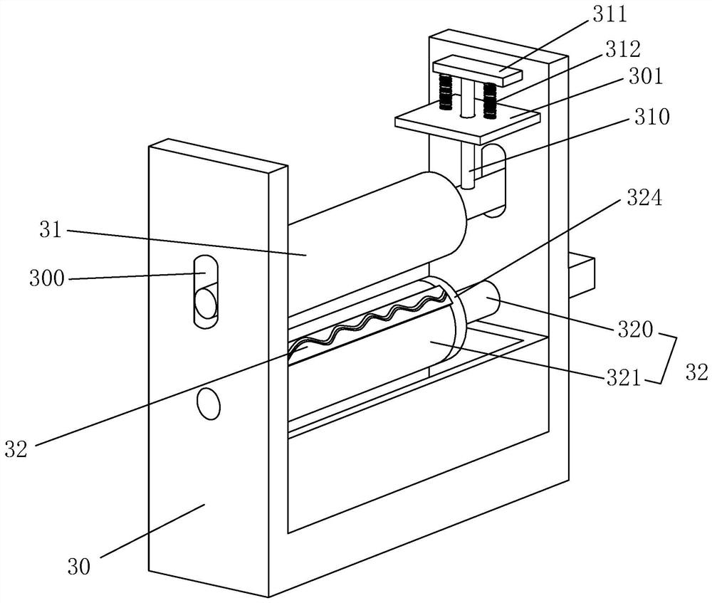
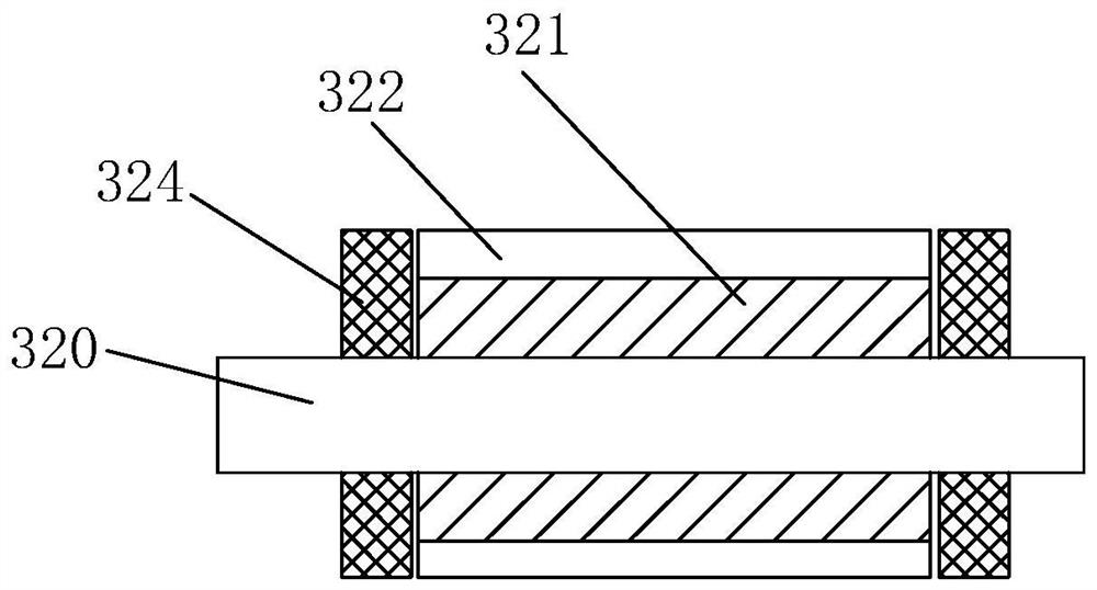
[0024] Reference Figure 1 to Figure 3 , A printing press, including a feeding mechanism, a conveying mechanism 2, an inking and embossing mechanism 3, and an unloading mechanism 4. The inking and embossing mechanism 3 includes a frame 30, a pressure roller 31 and a plate roller 32, a pressure roller 31 and Between the plate rollers 32 is formed a passage for the cardboard to pass through, the two sides of the frame 30 are respectively provided with slots 300, the pressure roller 31 is slidably arranged up and down in the slots 300, the roller shaft 320 Connecting rods 310 are provided at both ends. A support plate 301 is provided above the frame 30 corresponding to the slot 300. The support plate 301 is provided with a movable opening for the connecting rod 310 to pass through. One end of the connecting rod 310 A stopper 311 is connected after passing through the movable opening. Two compression springs 312 are provided between the stopper 311 and the supporting plate 301. The...


PUM


Abstract

The invention discloses a printer. Slotted holes are formed in the two sides of a rack correspondingly. A pressing roller is arranged in the slotted holes in an up-down sliding manner. Connecting rodsare arranged at the two ends of a roller shaft. Support plates are arranged at the upper parts, corresponding to the slotted holes, of the rack. The support plates are provided with movable ports forthe connecting rods to penetrate. One ends of the connecting rods are connected with stop blocks after penetrating through the movable ports. Two compression springs are arranged between each stop block and the corresponding support plate, wherein the compression springs are located at the two ends of the stop block. The compression springs drive the connecting rods to move in the roller shaft direction, and accordingly the pressing roller is driven to get close to a plate roller. The plate roller comprises the roller shaft and a roller, the roller is provided with a plurality of installing grooves arranged in the radial direction of the roller, the installing grooves are internally provided with detachable plate pattern blocks provided with protruding plate patterns, and the ends, with the plate patterns, of the plate pattern blocks extend out of the installing grooves. After improvement, the application range of the printer is wider, and the work efficiency is higher.

Description

Technical field [0001] The present invention relates to the technical field of printing equipment, and more specifically, it relates to a printing machine. Background technique [0002] A printing press is a machine that prints text and images. Including feeding mechanism, conveying mechanism, inking embossing mechanism and unloading mechanism. The ink-coating and embossing mechanism includes a pressing roller and a plate roller, and a passage for the cardboard to pass through is formed between the pressing roller and the plate roller. When working, the cardboard to be printed is placed on the feeding mechanism, and the cardboard is transported to the inking and embossing mechanism by the conveying mechanism, and rolled over the plate roller. The pressure roller drives the cardboard against the plate roller to make the cardboard on Images or text can be printed, and there is a conveying mechanism to convey the printed finished cardboard to the unloading mechanism for unloading....

Claims


Application Information

Patent Timeline
Patent Type & Authority Applications(China)
IPC IPC(8): B41F19/08B41F13/02B41F21/00
CPCB41F13/02B41F19/08B41F21/00
Inventor 缪寿者
Owner 瑞安市联华印刷机械有限公司
Why Eureka
Try Eureka