Ejection rack for unmanned aerial vehicle launching

A technology for ejection racks and unmanned aerial vehicles, which is applied in the field of ejection racks, can solve the problems of easy damage, complicated and laborious adjustment, inconvenient movement of ejection racks, etc., and achieves the effects of preventing reverse movement and easy operation.

Inactive Publication Date: 2020-10-13
山东万佳达电子科技有限公司
View PDF0 Cites 3 Cited by
  • Summary
  • Abstract
  • Description
  • Claims
  • Application Information

AI Technical Summary

Problems solved by technology

[0004] The invention proposes an ejection rack for launching drones, which solves the problems that the fixed rack cannot be stopped in time, is easily damaged, the ejection rack is inconvenient to move, and the adjustment is too complicated and laborious.

Method used


Image

  • Ejection rack for unmanned aerial vehicle launching
  • Ejection rack for unmanned aerial vehicle launching
  • Ejection rack for unmanned aerial vehicle launching

Examples


Embodiment Construction

[0024] The following will clearly and completely describe the technical solutions in the embodiments of the present invention with reference to the accompanying drawings in the embodiments of the present invention. Obviously, the described embodiments are only some, not all, embodiments of the present invention.

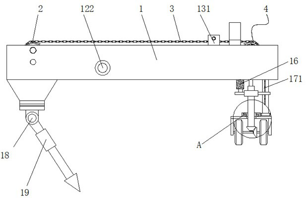
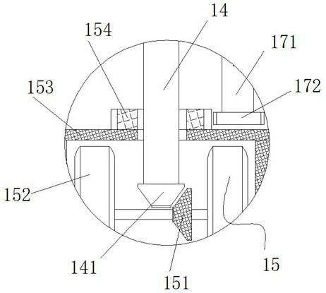
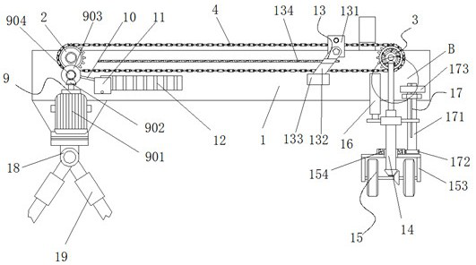
[0025] refer to Figure 1-6 , a catapult frame for unmanned aerial vehicles, including a support frame 1, the support frame 1 is composed of two fixed plates arranged in parallel, both ends of the fixed plate are fixed by iron rods, and the inner wall of one end of the support frame 1 is symmetrical A chain wheel 2 is provided, and a ratchet assembly 3 is provided on both sides of the inner wall of the support frame 1 away from the end of the chain wheel 2. The edge of the chain wheel 2 is connected to the ratchet assembly 3 through a chain 4, and the side of the chain wheel 2 is close to the fixed plate. Both are fixedly connected with driven gear 5, and the bottom ...


PUM


Abstract

The invention belongs to the technical field of unmanned aerial vehicles and relates to an ejection rack for unmanned aerial vehicle launching. An existing fixing frame cannot be stopped in time, theejection rack is easy to damage and inconvenient to move, and adjustment is too complex and strenuous. In order to solve the above problems, the following scheme is provided. A support frame is included. The supporting frame is composed of two fixing plates which are arranged in parallel. The two ends of each fixing plate are fixed through iron rods. Chain wheels are symmetrically arranged on an inner wall of one end of the supporting frame, ratchet wheel assemblies are arranged on the two sides of the inner wall of the end, away from the chain wheels, in the supporting frame, the edges of thechain wheels are in transmission connection with the ratchet wheel assemblies through chains, driven gears are fixedly connected to the sides, close to the fixing plates, of the chain wheels, and transmission gears are rotatably engaged with the bottoms of the driven gears. The ejection rack has advantages that an unmanned aerial vehicle fixing device can be stopped slowly, collision is prevented, steering movement is performed automatically, and labor is saved.

Description

technical field [0001] The invention relates to the technical field of unmanned aerial vehicles, in particular to a catapult rack for launching unmanned aerial vehicles. Background technique [0002] There are already a large number of UAV enthusiasts in our country. There are many types of small UAVs. Traditional fixed-wing UAVs usually need external force to take off. Traditional takeoff methods usually use catapults or hand-throwing to take off. When taking off, it needs to be in an open place. When launching, the fixed frame drives the aircraft to move, and when it reaches the end of the track, it separates. [0003] The structure of the traditional UAV ejection frame is too simple. After separation, the fixed frame will continue to move under the inertia of the motor or other power. At this time, it is necessary to set up a blocking device to stop the fixed frame through impact. During the use process, it will cause damage and deformation of the fixing frame, resulting...

Claims


Application Information

Patent Timeline
Patent Type & Authority Applications(China)
IPC IPC(8): B64F1/06
CPCB64F1/06B64U70/70
Inventor 刘占波
Owner 山东万佳达电子科技有限公司
Why Eureka
Try Eureka