Bridge quakeproof buffer device and quakeproof bridge

A buffer device and bridge technology, which is applied in bridges, bridge parts, bridge materials, etc., can solve the problems of unfavorable influence of bridge structure safety, large earthquake response of main girder, etc., achieve low engineering cost, improve seismic performance, and reduce lateral The effect of displacement

Pending Publication Date: 2020-10-13
SICHUAN DEPT OF TRANSPORTATION HIGHWAY PLANNING PROSPECTING & DESIGN RES INST
View PDF0 Cites 3 Cited by
  • Summary
  • Abstract
  • Description
  • Claims
  • Application Information

AI Technical Summary

Problems solved by technology

[0004] The purpose of the present invention is to solve the problem in the prior art that for long-span bridges, under the action of earthquake force, the longitudinal and lateral directions of the main gir

Method used


Image

  • Bridge quakeproof buffer device and quakeproof bridge
  • Bridge quakeproof buffer device and quakeproof bridge
  • Bridge quakeproof buffer device and quakeproof bridge

Examples


Embodiment 1

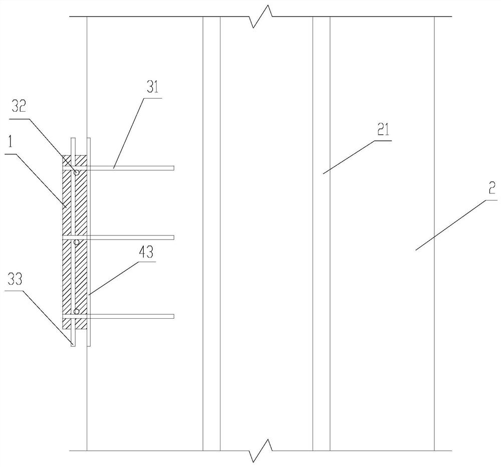
[0037] Such as Figure 1-Figure 3 As shown, a bridge anti-vibration cushioning device includes a shock-absorbing cushion block 1, and the shock-absorbing cushion block 1 is a polyurethane cushion block or a shock-absorbing rubber cushion block, and one side of the shock-absorbing cushion block 1 is provided with Block 2, the block 2 is a concrete structure, a plurality of flexible mortar columns 21 are vertically arranged in the block 2, and a plurality of flexible mortar columns 21 are arranged at intervals in the block 2, the The flexible mortar column 21 is a cement mortar column.

[0038] The stopper 2 is fixedly connected with the shock absorbing cushion block 1. Specifically, the shock absorbing cushion block 1 is penetrated with a perforated steel bar 32, and the stopper 2 is provided with a pre-embedded steel bar 31. The pre-embedded steel bars 31 are arranged perpendicular to the shock-absorbing cushion block 1, the perforated steel bars 32 are horizontally arranged ...

Embodiment 2

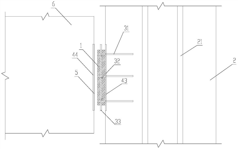
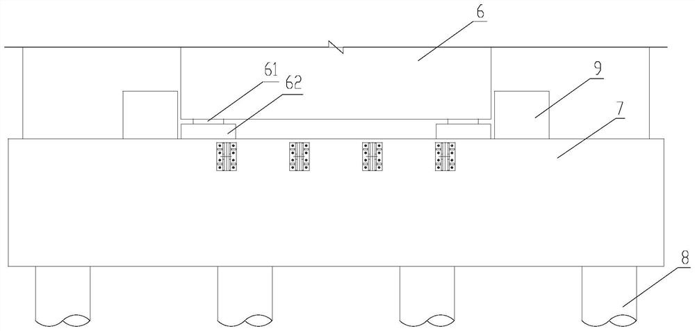
[0042] Such as Figure 2-Figure 4 As shown, a kind of anti-seismic bridge comprises several piers and abutments 7, a main girder 6 is arranged above the piers and the abutments 7, and each abutment 7 is fixedly connected with a support pad stone 62, The support pad 62 is provided with a support 61 , and the main beam 6 is placed on the support 61 . A pile foundation 8 is connected below the abutment 7, and the pile foundation is fixedly connected with the ground.

[0043] Each abutment 7 is fixedly connected with two bridge anti-vibration buffer devices 9, and the bridge anti-vibration buffer devices 9 are respectively arranged on both sides of the main girder 6 along the transverse direction, and are provided with the shock-absorbing One side of the cushion block 1 faces the main beam 6, and the two sides of the main beam 6 are respectively provided with embedded steel plates 44, and the embedded steel plates 44 are matched with the shock-absorbing cushion block 1 , The emb...


PUM


Abstract

The invention relates to the technical field of bridge earthquake resistance, and particularly relates to a bridge quakeproof buffer device and a quakeproof bridge, wherein the bridge quakeproof buffer device comprises a shock-absorbing buffer cushion block, a stop block is arranged on one side of the shock-absorbing buffer cushion block, and the stop block is fixedly connected with the shock-absorbing buffer cushion block. The quakeproof bridge comprises a plurality of bridge piers and a bridge abutment, wherein a main beam is arranged above the bridge piers and the bridge abutment, the bridge abutment is fixedly connected with at least two bridge quakeproof buffer devices, the bridge quakeproof buffer devices are arranged on the two sides of the main beam in the transverse direction respectively, and the side, which is provided with the shock-absorbing buffer cushion block, of the bridge quakeproof buffer device faces the main beam. According to the bridge quakeproof buffer device, the stop blocks are fixed to the bridge abutment, the buffering and anti-collision effects of the shock-absorbing buffer cushion blocks are utilized, the transverse impact effect of the main beam is reduced, the transverse earthquake resistant performance of a bridge is improved, the safety of a bridge structure is improved, construction is facilitated when the bridge quakeproof buffer device is arranged on the bridge abutment, and the invested engineering cost is low.

Description

technical field [0001] The invention relates to the field of bridge anti-seismic technology, in particular to a bridge anti-seismic buffer device and an anti-seismic bridge. Background technique [0002] For bridges built in high-intensity earthquake areas, under the action of earthquake force, the longitudinal and transverse seismic responses of the main girder of the bridge will have a large seismic response, which will have a very adverse effect on the safety of the bridge structure. The longitudinal direction and the transverse direction refer to the direction along the bridge and the direction across the bridge respectively. [0003] Therefore, the bridge structure needs to have high seismic performance. The traditional seismic method relies on the elastic-plastic deformation of components to absorb seismic energy. In order to meet the seismic requirements of bridge structures, methods of enlarging component sections or strengthening structural rigidity are often used....

Claims


Application Information

Patent Timeline
IPC IPC(8): E01D19/00E01D101/26
CPCE01D19/00E01D2101/26
Inventor 钟川剑李成君梁健范碧琨李胜王戈古锐傅支黔王建张彩楼
Owner SICHUAN DEPT OF TRANSPORTATION HIGHWAY PLANNING PROSPECTING & DESIGN RES INST
Why Eureka
Try Eureka