
Self-cleaning photovoltaic power generation panel for street lamp

A photovoltaic power generation panel and self-cleaning technology, applied in the direction of photovoltaic power generation, photovoltaic modules, electric light sources, etc., can solve the problems that photovoltaic panels are easy to absorb dust, affect the power generation efficiency of photovoltaic panels, and damage photovoltaic panels, so as to improve the dust cleaning effect, Good dust removal effect, guarantee the effect of normal use

Inactive Publication Date: 2020-10-13
杨李强
View PDF7 Cites 1 Cited by
  • Summary
  • Abstract
  • Description
  • Claims
  • Application Information

AI Technical Summary

Problems solved by technology

[0004] The purpose of the present invention is to solve the shortcomings in the prior art that the photovoltaic panels used in street lamps are easy to absorb dust in practice, thereby affecting the power generation efficiency of the photovoltaic panels, and at the same time causing damage to the photovoltaic panels, and propose a street lamp. Self-cleaning photovoltaic panels

Method used


Image

  • Self-cleaning photovoltaic power generation panel for street lamp
  • Self-cleaning photovoltaic power generation panel for street lamp
  • Self-cleaning photovoltaic power generation panel for street lamp

Examples


Embodiment 1

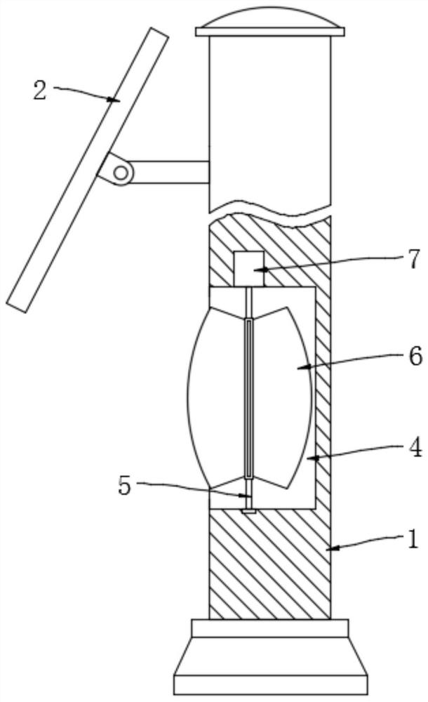
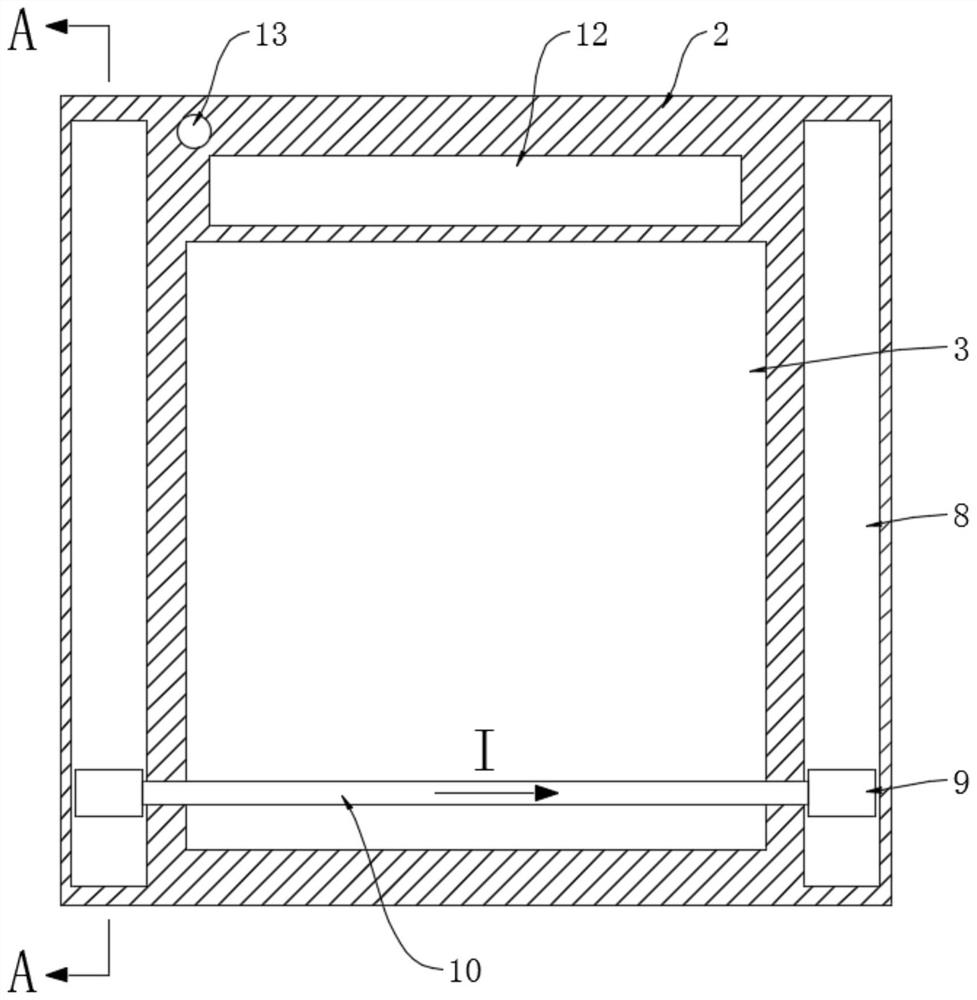
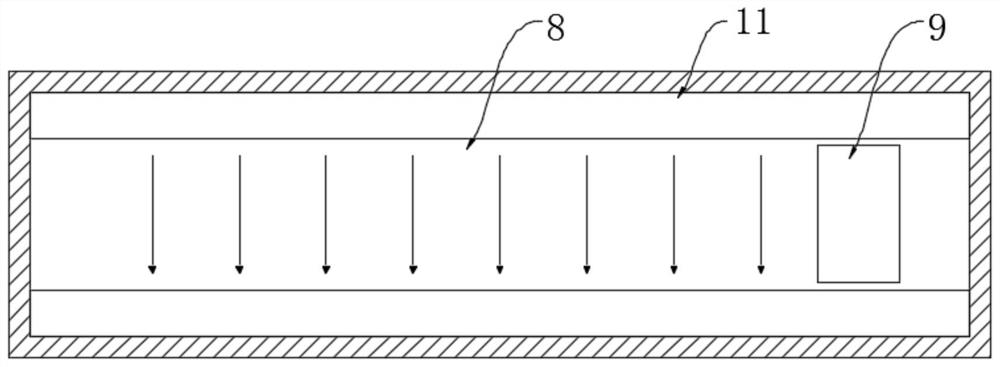
[0026] refer to Figure 1-3 , a self-cleaning photovoltaic power generation panel for street lamps, including a street lamp body 1 and a photovoltaic panel 3 mounted on the street lamp body 1 through a frame 2, the street lamp body 1 is provided with a mounting groove 4, and the notch of the mounting groove 4 is facing the road Drive fan 6 is installed in the installation groove 4 through vertically rotating rotating shaft 5, and a micro-generator 7 is also installed on the street lamp body 1, and one end of the rotating shaft 5 is connected to the input end of the micro-generator 7, namely One end of the rotating shaft 5 is fixedly connected with the rotor of the micro generator 7;

[0027] Two slide slots 8 are symmetrically opened on the frame 2, and a conductive block 9 is slidably connected to each slide slot 8, and a conductive rod 10 is fixedly connected between the two conductive blocks 9, and when the conductive rod 10 is located above the photovoltaic panel 3 , its ...

Embodiment 2

[0030] Embodiment 2. The difference between this embodiment and Embodiment 1 is that: the frame 2 is provided with an ash storage tank 15 communicated with the ash collecting hopper 12, and the ash storage tank 15 is provided with a dust-proof net 16, and each chute 8 Elastic airbags 14 are arranged inside, and each elastic airbag 14 is connected with the ash storage tank 15 with a one-way air intake pipe 17, and the connection between each one-way air intake pipe 17 and the ash storage tank 15 is located in the dust-proof area. Below the net 16, each elastic air bag 14 is connected with a one-way exhaust pipe 18, and the one-way air intake pipe 17 only allows the gas in the ash storage tank 15 to enter in the elastic air bag 14 through the one-way air intake pipe 17, and the one-way exhaust The air pipe 18 only allows the gas in the elastic air bag 14 to be discharged to the outside through the one-way exhaust pipe 18 .

[0031] When using this embodiment, firstly, during the...


PUM


Abstract

The invention discloses a self-cleaning photovoltaic power generation panel for a street lamp, comprising a street lamp body and a photovoltaic panel mounted on the street lamp body through a frame. Amounting groove is formed in the street lamp body, a driving fan is rotationally mounted in the mounting groove through a rotating shaft, a micro-generator is further mounted on the street lamp body,and one end of the rotating shaft is connected with the input end of the micro-generator. Airflow generated by a running vehicle is used as power, the photovoltaic panel of the street lamp can be automatically subjected to ash removal treatment, input of external energy is not needed, the concept of new energy is met, meanwhile, repeated operation can be achieved, and the ash removal effect is good.

Description

technical field [0001] The invention relates to the field of new energy technologies, in particular to a self-cleaning photovoltaic power generation panel for street lamps. Background technique [0002] In recent years, with the shortage of petroleum energy worldwide, and the environmental problems caused by the use of petroleum energy have become more and more serious, all countries are vigorously developing various new energy sources that can be used. New energy is also called unconventional energy. It refers to Various forms of energy other than traditional energy, such as solar energy, geothermal energy, wind energy, ocean energy, biomass energy and nuclear fusion energy, among which solar energy is clean and environmentally friendly, without any pollution, high utilization value, and solar energy is sustainable The great advantage of energy without energy shortage makes it occupy an extremely important position in energy replacement. [0003] The use of photovoltaic po...

Claims


Application Information

Patent Timeline
Patent Type & Authority Applications(China)
IPC IPC(8): F21S9/03F21V31/00H02S40/10H02K7/18F21W131/103
CPCF21S9/035F21V31/00F21W2131/103H02K7/183H02K7/1861H02S40/10Y02B20/72Y02E10/50
Inventor 杨李强吴苗苗
Owner 杨李强
Learn More