Dust falling device for building blasting

A dust suppression device and construction technology, which is applied in the field of construction, can solve the problems of inability to deal with dust and dust, and achieve the effect of preventing the reduction of dust removal efficiency and facilitating dust removal and treatment

Inactive Publication Date: 2020-10-13
袁国初
View PDF1 Cites 3 Cited by
  • Summary
  • Abstract
  • Description
  • Claims
  • Application Information

AI Technical Summary

Problems solved by technology

The blasting dust suppression device near the aviation oil pipeline building in the above patent has the following disadvantages: when the existing device is used for dust reduction treatment, the dust may fly to a high place, resulting in the device not being able to effectively reduce dust. deal with

Method used


Image

  • Dust falling device for building blasting
  • Dust falling device for building blasting
  • Dust falling device for building blasting

Examples


Embodiment 1

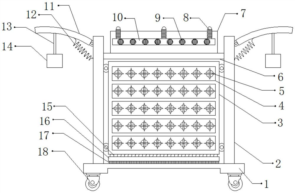
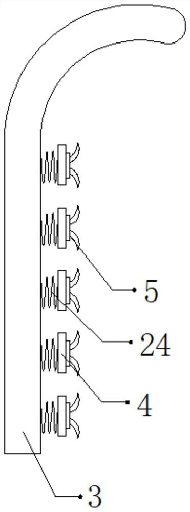
[0028] refer to Figure 1-3 , a dust suppression device for building blasting, comprising a fixed base 1, the two sides of the top outer wall of the fixed base 1 are connected with a fixed plate 2 by bolts, and the outer walls of one side of the two fixed plates 2 are connected with blades 11 through a hinge, the blades 11 and one side outer wall of the fixed plate 2 are connected with a first spring 12 by bolts, the bottom outer walls of the two blades 11 are bolted with suspension ropes 13, and the bottom outer walls of the two suspension ropes 13 are bolted with fixed blocks 14. A baffle plate 3 is connected by a hinge between the outer walls on the opposite side of the two fixed plates 2, and a support plate 6 is connected by bolts between the outer walls on the opposite side of the two fixed plates 2, and the top of the support plate 6 The outer wall is connected with a water storage tank 7 by bolts, a water inlet is provided on one side of the top outer wall of the water...

Embodiment 2

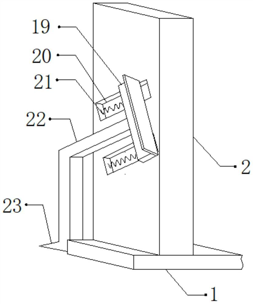
[0038] refer to Figure 4, a dust suppression device for building blasting. Compared with Embodiment 1, the outer wall of the bottom of the fixed base 1 is connected with a hydraulic rod 27 by bolts, and the outer wall of the bottom of the hydraulic rod 27 is connected with an anti-skid plate 25 by bolts. The anti-skid plate The bottom outer wall of 25 is provided with a plurality of equidistantly distributed tooth blocks 26 .

[0039] Working principle: When in use, move the device to a suitable position through the moving wheel 19, start the hydraulic rod 27, and the hydraulic rod 27 will drive the anti-skid plate 25 to move down, and the friction between the device and the ground can be increased through the gear block 26 , in order to fix the device, when the blasting is completed, the fixed block 14 will swing due to the impact force, so that the swing of the fixed block 14 will drive the blade 11 to swing up and down, so that the wind force generated when the blade 11 sw...


PUM


Abstract

The invention discloses a dust falling device for building blasting. The dust falling device comprises a fixing seat, wherein fixing plates are fixedly connected to two sides of the outer wall of thetop of the fixing seat; blades are connected to the outer walls of one sides of the two fixing plates through hinges; first springs are fixedly connected between the blades and the outer walls of onesides of the fixing plates; lifting ropes are bolted to the outer walls of the bottoms of the two blades; fixing blocks are bolted to the outer walls of the bottoms of the two lifting ropes; a baffleis connected between the outer walls of the opposite sides of the two fixing plates through hinges; and a supporting plate is fixedly connected between the outer walls of the opposite sides of the twofixing plates. According to the dust falling device disclosed by the invention, the condition that the device cannot effectively perform dust falling treatment on dust due to the fact that the dust flies upwards can be avoided, the condition that the device falls due to impact force generated during blasting so as to influence dust falling of the device can be avoided, and the condition that thedust removal efficiency of the device is reduced due to high flowing speed of the dust can be avoided.

Description

technical field [0001] The invention relates to the technical field of construction, in particular to a dust suppression device for construction blasting. Background technique [0002] When buildings need to be demolished in municipal planning, for high-rise buildings, in order to improve their demolition efficiency, explosive blasting is often used to blow them down, and then gradually dispose of the ruins after blasting. However, dust will be generated during the blasting process. Therefore, dust suppression is required. The device performs dust reduction treatment on dust. [0003] After retrieval, the Chinese patent authorization number is CN110479011A, which discloses a construction blasting and dust suppression device near aviation oil pipelines, including a water tank. There is a rotating slot, and a water pipe is inserted into the inside of the rotating slot, and a positioning hole is opened on the outer wall of the water pipe, and a brake screw is inserted into the...

Claims


Application Information

Patent Timeline
Patent Type & Authority Applications(China)
IPC IPC(8): F42D3/02F42D5/00
CPCF42D3/02F42D5/00
Inventor 袁国初
Owner 袁国初
Why Eureka
Try Eureka