Eureka AIR delivers breakthrough ideas for toughest innovation challenges, trusted by R&D personnel around the world.

Cable for new energy automobile

A new energy vehicle and cable technology, applied in the direction of insulated cables, cables, circuits, etc., can solve the problems of local heat generated by friction parts, fire at gas filling stations, hidden safety hazards, etc., and achieve excellent heat conduction and heat dissipation, good mechanical strength, The effect of low manufacturing cost

Active Publication Date: 2020-10-13
ANHUI LINGYU CABLE TECH +1
View PDF15 Cites 2 Cited by
  • Summary
  • Abstract
  • Description
  • Claims
  • Application Information

AI Technical Summary

Problems solved by technology

However, there are also some disadvantages in the use of cables for new energy vehicles; for example, when new energy vehicles are refueled at gas stations, the cables are often dragged, and they are also prone to collisions with other things during the dragging process. In addition, during the dragging process, it is easy to generate friction with the ground, which will cause local heat to be generated at the friction part. During the peak period of refueling, continuous dragging of the cable is likely to cause fire due to excessive local temperature. A fire broke out in the entire gas filling station, causing serious safety hazards

Method used


Image

  • Cable for new energy automobile
  • Cable for new energy automobile
  • Cable for new energy automobile

Examples


Embodiment 1

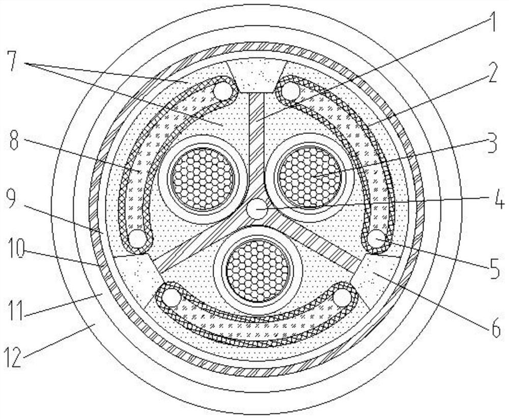
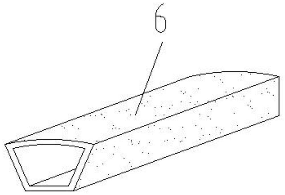
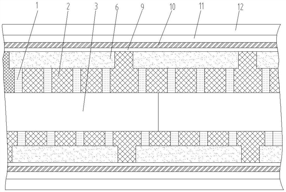
[0025] see Figure 1-3 , a cable for new energy vehicles, comprising a cable body, and the cable body includes a cable core and a cable core protective sleeve covering the surface of the cable core, and the gap in the cable core protective sleeve except the cable core is filled with fiber filler Object 7, the cable core protective cover sequentially includes a water-blocking wrapping layer 9, a shielding layer 10, an inner sheath 11 and an outer sheath 12 from the inside and outside, and the material of the water-blocking wrapping layer 9 is PE material, It has better electrical insulation and hydrophobicity, and the manufacturing cost is low. The inner sheath 11 is a flame-retardant material made of PVC modifier and PVC, so that the cable body has better flame-retardant Performance, the outer sheath 12 is made of LLDPE material, so that it has high electrical insulation, high heat resistance, impact resistance and puncture resistance, and also has excellent environmental stre...

Embodiment 2

[0035] see figure 1 , 2 And 4, the difference between embodiment two and embodiment one is:

[0036] In this embodiment, the length of the buffer profiled bracket 1 is equal to the length of the power slider 6 .

[0037] Others are the same as embodiment one.


PUM


Abstract

The invention discloses a cable for a new energy automobile. The cable comprises a cable body, and the cable body comprises a cable core and a cable core protective sleeve wrapping the surface of thecable core. The cable core protective sleeve sequentially comprises a water-blocking wrapping layer, a shielding layer, an inner protection layer and an outer protection layer from inside to outside.The cable core comprises a buffer special-shaped bracket with a Y-shaped cross section, wires which are distributed at included angles of the buffer special-shaped bracket, power sliding blocks whichare positioned at the top ends of support legs of the buffer special-shaped bracket and are attached to the inner side of the water-blocking wrapping layer, and compression-resistant protection bodiespositioned on the outer sides of the wires; a buffer deformation cavity parallel to the length direction of the cable body is formed in the central position of the buffer special-shaped bracket; under the action of the buffer special-shaped bracket, the power sliding blocks and the compression-resistant protection bodies, the wires can properly move left and right in a cable protection sleeve inthe circumferential direction of the cable body so that a force unloading effect on the wires is achieved, and the cable body further has the functions of high flame retardance and high heat dissipation.

Description

technical field [0001] The invention relates to the technical field of cables for new energy vehicles, in particular to a cable for new energy vehicles. Background technique [0002] As people's living standards are getting higher and higher, people's awareness of the protection of the earth's environment in their own residences is gradually increasing, and non-environmental protection products have been eliminated. Especially now that the means of transportation are becoming more and more environmentally friendly, and with the strong support of the state, as the technology of new energy vehicles becomes more and more mature, the use of new energy vehicles is increasing. However, there are also some disadvantages in the use of cables for new energy vehicles; for example, when new energy vehicles are refueled at gas stations, the cables are often dragged, and they are also prone to collisions with other things during the dragging process. In addition, during the dragging pro...

Claims


Application Information

Patent Timeline
Patent Type & Authority Applications(China)
IPC IPC(8): H01B7/29H01B7/295H01B7/42H01B7/28H01B7/282H01B7/18H01B3/44
CPCH01B3/44H01B3/443H01B7/18H01B7/185H01B7/1875H01B7/1895H01B7/28H01B7/2825H01B7/292H01B7/295H01B7/421H01B7/428
Inventor 李万松丁运生
Owner ANHUI LINGYU CABLE TECH
Why Eureka
Eureka Blog
Learn More